Blocked Rotor Test of an Induction Motor

The blocked - rotor test of an induction motor is analogous to the short - circuit test of a transformer. In this test, the motor's shaft is immobilized to prevent any rotation, and the rotor winding is short - circuited. For a slip - ring motor, the rotor winding is short - circuited via the slip rings. In the case of cage motors, the rotor bars are inherently short - circuited. This test is also referred to as the Locked Rotor Test. The circuit diagram for the blocked - rotor test is presented below:
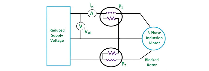
A reduced voltage at a reduced frequency is supplied to the stator via a three - phase autotransformer, ensuring that the full - load rated current circulates in the stator. The blocked - rotor test yields the following three measurements:

Reading of the voltmeter

where cosϕ represents the power factor of the short - circuit. The equivalent resistance of the motor, referred to the stator side, is expressed by the following equation:

The equivalent impedance of the motor referred to the stator side is given by the equation shown below:

The equivalent reactance of the motor referred to the stator side is given by the equation shown below.

The blocked - rotor test is carried out under normal operating conditions, with the rotor current and frequency being in their typical states. Generally, for an induction motor, the slip typically ranges from 2% to 4%. When the stator frequency is 50 hertz under normal conditions, the resulting rotor frequency falls within the range of 1 to 2 hertz.
This test should be executed at a reduced frequency. To achieve accurate results, the blocked - rotor test is performed at a frequency that is 25% or less of the rated frequency. The leakage reactances at the rated frequency are derived based on the principle that reactance is proportional to frequency.
Nevertheless, for motors with a rating of less than 20 kilowatts, the influence of frequency is negligible, and the blocked - rotor test can be directly conducted at the rated frequency.


