Differences Between Rectifier Transformers and Power Transformers
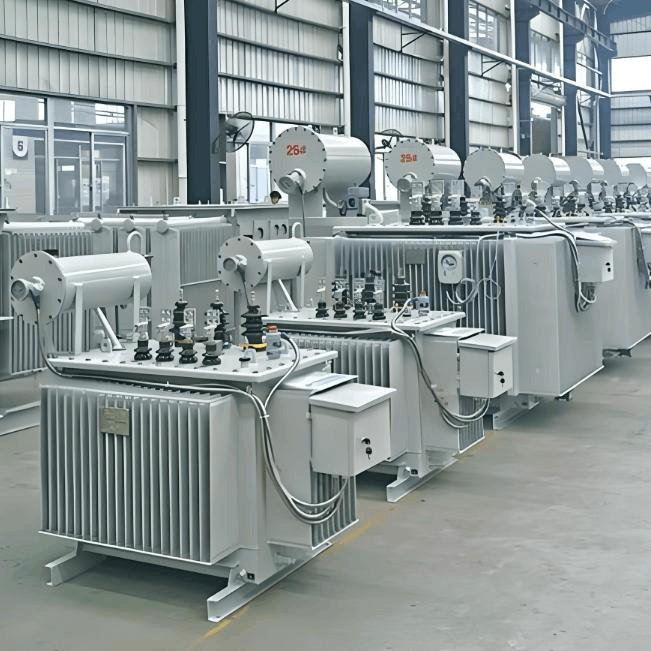
Rectifier transformers and power transformers both belong to the transformer family, but they differ fundamentally in application and functional characteristics. The transformers commonly seen on utility poles are typically power transformers, while those supplying electrolytic cells or electroplating equipment in factories are usually rectifier transformers. Understanding their differences requires examining three aspects: working principle, structural features, and operating environment.
From a functional perspective, power transformers primarily handle voltage level conversion. For example, they step up generator output from 35 kV to 220 kV for long-distance transmission, then step it down to 10 kV for community distribution. These transformers act like movers in the power system, focusing solely on voltage transformation. In contrast, rectifier transformers are designed for AC-to-DC conversion, typically paired with rectifying devices to convert AC into specific DC voltages. For instance, in metro traction systems, rectifier transformers convert grid AC power into 1,500 V DC to drive trains.
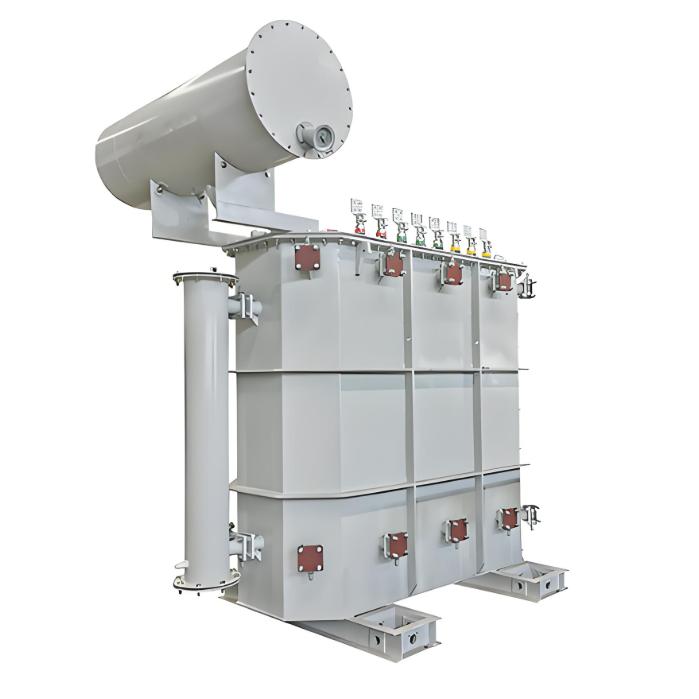
Structural design reveals significant distinctions. Power transformers emphasize linear voltage transformation, with precise turns ratios between high- and low-voltage windings. Rectifier transformers, however, must account for harmonics generated during rectification. Their secondary windings often use special configurations—such as multiple branches or delta connections—to suppress specific harmonic orders. For example, the ZHSFPT model from one manufacturer employs a three-winding structure with phase-shift design to effectively reduce 5th and 7th harmonic pollution on the grid.
Core material selection also reflects functional needs. Power transformers commonly use standard grain-oriented silicon steel for low loss and high efficiency. Rectifier transformers, subjected to non-sinusoidal currents, often employ high-permeability cold-rolled silicon steel; some high-power models even use amorphous alloy cores. Test data show that, under the same capacity, rectifier transformers typically have 15%–20% higher no-load losses than power transformers due to their unique operational stresses.
Operating conditions differ drastically. Power transformers run under relatively stable loads, with a fixed grid frequency of 50 Hz and ambient temperatures ranging from -25°C to 40°C. Rectifier transformers face complex conditions: aluminum electrolysis plants may experience dozens of load fluctuations daily, with instantaneous current surges exceeding rated values by 30%. Field measurements from a smelter show that winding hotspot temperatures in rectifier transformers can spike from 70°C to 105°C during electrolyzer startup, demanding higher thermal stability from insulation materials.
Protection designs vary accordingly. Power transformers focus on lightning and moisture protection, typically with IP23 rating. Rectifier transformers, often installed in industrial environments with corrosive gases, use stainless steel enclosures and higher protection levels such as IP54. Some chemical plants even equip their rectifier transformers with pressurized ventilation systems to prevent acid gas ingress.

Maintenance cycles also differ. Standard power transformers undergo core inspection every six years per national regulations. However, maintenance records from a steel group reveal that rectifier transformers in continuous casting lines require seal replacement every two years and winding deformation tests every three years, due to accelerated aging from stronger mechanical stresses under rectifying conditions.
Cost structures vary significantly. For a 1,000 kVA unit, a standard power transformer costs about 250,000 RMB, while a comparable rectifier transformer typically costs over 40% more. This stems from increased material usage due to complex winding structures and added harmonic suppression components. Production data from one factory show rectifier transformers use 18% more copper and 12% more silicon steel than equivalent power transformers.
Application scenarios are clearly distinct. Power transformers are ubiquitous in substations, residential areas, and commercial complexes, performing fundamental power distribution. Rectifier transformers serve specialized industries: rail transit traction substations, chlor-alkali plant electrolysis rooms, and PV station inverter systems. In renewable energy, for example, one solar farm deployed 24 rectifier transformers to invert DC from photovoltaic panels into grid-compatible AC.
Technical parameters also differ. Power transformers typically have short-circuit impedances of 4%–8%, optimized for system stability. Rectifier transformers require precise impedance calculation; design documents for one model specify 8.5% to limit fault current and ensure safe rectifier operation. Regarding temperature rise, power transformers limit top-oil temperature to 95°C, while rectifier transformers allow temporary peaks up to 105°C, as explicitly stated in technical specifications.
Energy efficiency standards diverge. Power transformers must comply with GB 20052 efficiency grades, with strict limits on no-load and load losses for Class I efficiency. Rectifier transformers are not yet covered by mandatory national efficiency standards, though leading manufacturers follow IEEE C57.18.10. Comparative test data show advanced rectifier transformers achieve 12% higher overall efficiency than conventional models, saving tens of thousands of RMB annually in electricity costs.
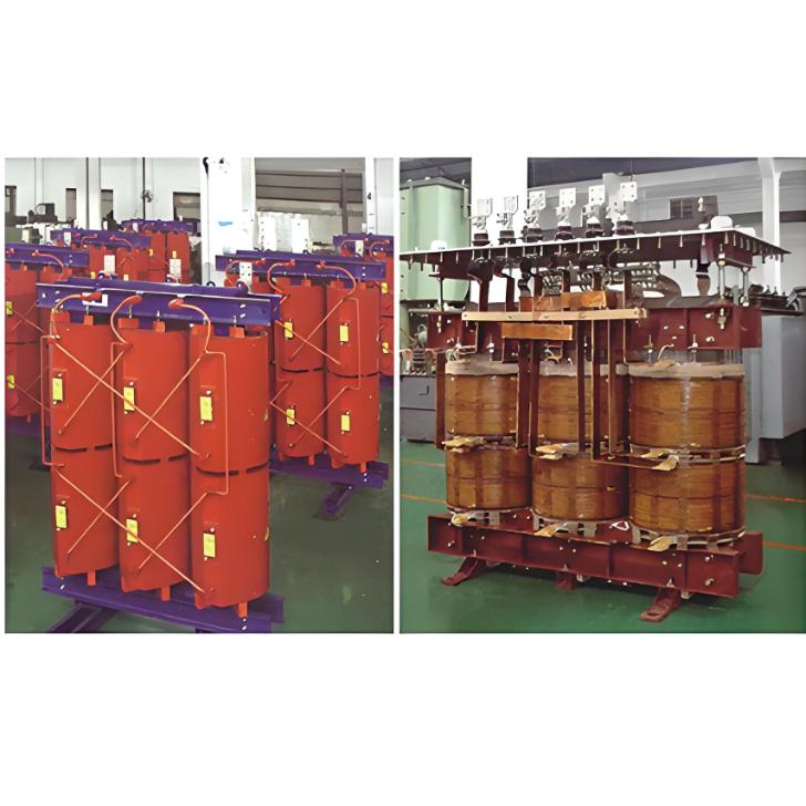
Selection depends heavily on application. For a residential distribution room, an SCB13 dry-type power transformer suffices. For an electroplating line, a rectifier transformer with a balancing reactor—like the ZHS series—is essential. A cautionary tale comes from an auto plant that mistakenly used a standard power transformer for electrophoretic coating, causing core saturation due to DC offset and resulting in winding burnout within three months.
Future trends are diverging. Power transformers are advancing toward intelligence, with many new models integrating online monitoring. Rectifier transformers continue breakthroughs in harmonic mitigation; one brand’s latest model uses dynamic voltage regulation to reduce input-side harmonic distortion from 28% to below 5%. These technological evolutions align closely with their respective application demands.