• Product
  • Suppliers
  • Manufacturers
  • Solutions
  • Free tools
  • Knowledges
  • Experts
  • Communities
Search


How Electrical Drives are Controlled ?

Encyclopedia
Encyclopedia
Field: Encyclopedia
0
China

How Electrical Drives are Controlled ?

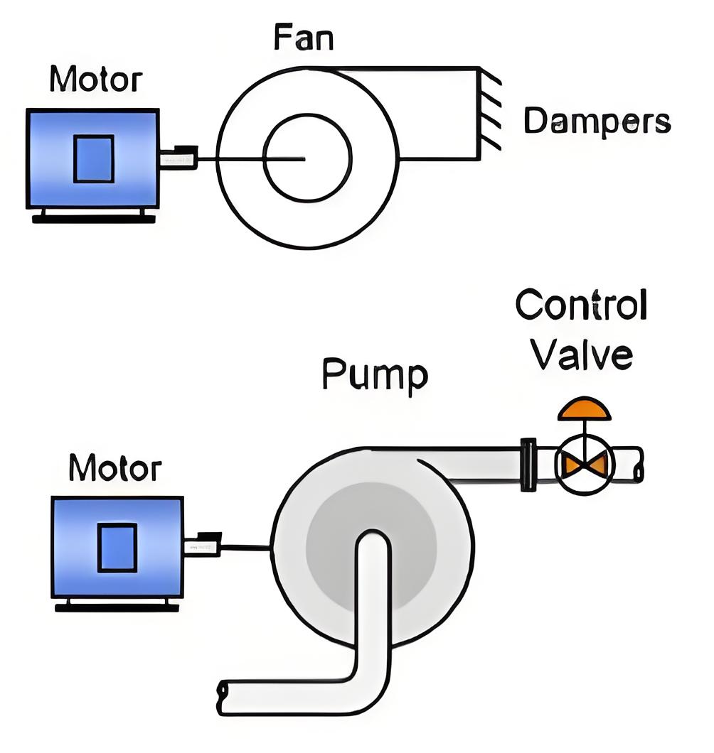
Electrical Drives Definition

Electrical drives are systems that control the operation of electric motors, including starting, speed control, and braking.

fefd0b29b630e813a0c997f9211ff439.jpeg

Importance of Control

Controlling electrical drives is essential to prevent damage from sudden changes in voltage or current.

Closed Loop Control

Control systems can be open loop or closed loop control system. In an open loop control system, the output does not affect the input, making the control independent of the output. In contrast, a closed loop system uses feedback from the output to adjust the input. If the output exceeds a set value, the input is reduced, and vice-versa. closed loop control system in electrical drives helps protect the system, enhance response speed, and improve accuracy.

  • Protection

  • Enhancement of speed of response

  • To improve steady-state accuracy

In the following discussions, we will see through different closed loop configurations which are used in electrical drives irrespective of the type of supply they are fed, i.e DC or AC.

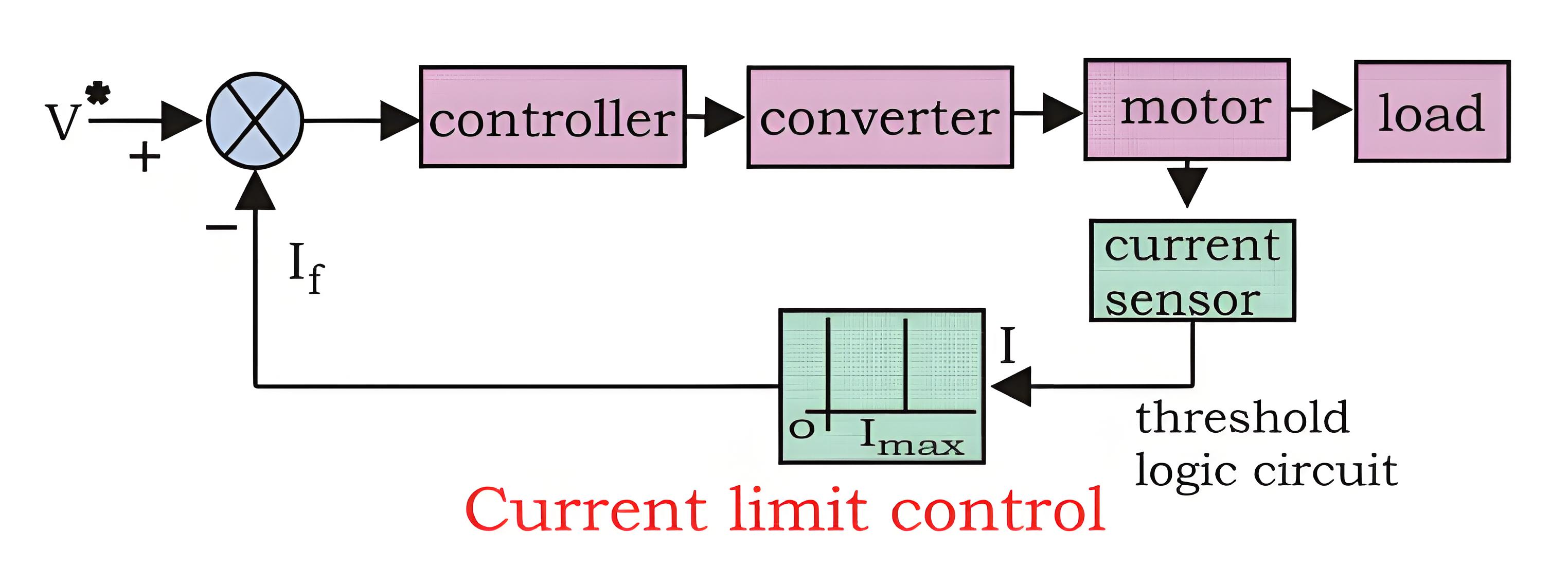
Current Limit Control

During start-up, motors can experience a huge current flow if precautions are not taken. A current limit controller is used to manage this. It monitors the current and, if it exceeds safe limits, the feedback loop activates to reduce the current. Once it’s back to a safe level, the feedback loop deactivates, ensuring normal operation.

5da80a20890f50452086ce8cf2b42e50.jpeg

Closed Loop Torque Control

This type of torque controller is seen mainly in battery operated vehicles like cars, trains etc. the accelerator present in the vehicles is pressed by the driver to set the reference torque T. The actual torque T follows the T which is controlled by the driver via accelerator.*

f57e7e2d9843bc1dcf8cc72fa05cf4c9.jpeg

Closed Loop Speed Control

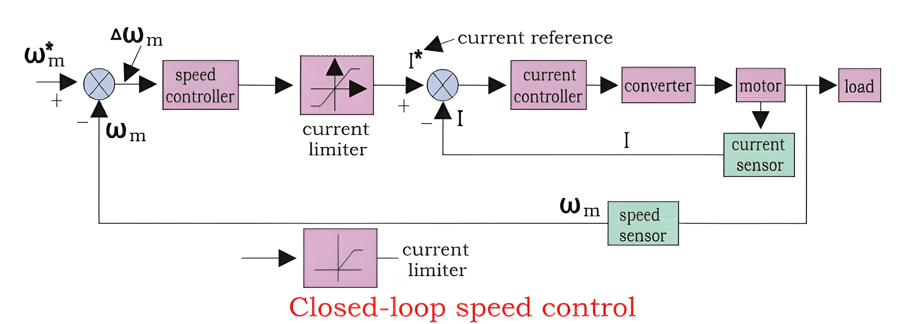
Speed control loops are widely used feedback loops in electrical drives. Looking at a block diagram can help understand how they work.

We can see from the diagram that there are two control loops, which can be said as an inner loop and outer loop. The inner current control loop limits the converter and motor current or motor torque below the safe limit. Now we can understand the function of the control loop and drive by practical examples. Suppose the reference speed W m* increases and there is a positive error ΔWm, which indicates that the speed is needed to be increased.

Now the inner loop increases the current keeping it under maximum allowable current. And then the driver accelerates, when the speed reaches the desired speed then the motor torque is equal to the load torque and there is a decrease in the reference speed Wm which indicates that there is no need of any more acceleration but there must be deceleration, and braking is done by the speed controller at maximum allowable current. So, we can say that during speed controlling the function transfers from motoring to braking and from braking to motoring continuously for the smooth operation and running of the motor.

a369609206a18763570a2394b97f59f2.jpeg

Give a tip and encourage the author!
Recommended
Top 5 Critical Process Controls for GIS Installation & Commissioning
This paper briefly outlines the advantages and technical characteristics of GIS (Gas-Insulated Switchgear) equipment, and elaborates on several critical quality control points and process control measures during on-site installation. It emphasizes that on-site withstand voltage tests can only partially reflect the overall quality and installation workmanship of GIS equipment. Only by strengthening comprehensive quality control throughout the entire installation process—especially in key areas su
James
10/29/2025
SST Technology: Full-Scenario Analysis in Power Generation, Transmission, Distribution, and Consumption
I. Research BackgroundPower System Transformation NeedsChanges in energy structure are placing higher demands on power systems. Traditional power systems are transitioning toward new-generation power systems, with the core differences between them outlined as follows: Dimension Traditional Power System New-Type Power System Technical Foundation Form Mechanical Electromagnetic System Dominated by Synchronous Machines and Power Electronic Equipment Generation-Side Form M
Echo
10/28/2025
SST Transformer Core Loss Calculation and Winding Optimization Guide
SST High-Frequency Isolated Transformer Core Design and Calculation Material Characteristics Impact:Core material exhibits varying loss behavior under different temperatures, frequencies, and flux densities. These characteristics form the foundation of overall core loss and require precise understanding of nonlinear properties. Stray Magnetic Field Interference:High-frequency stray magnetic fields around windings can induce additional core losses. If not properly managed, these parasitic losses
Dyson
10/27/2025
Design of a Four-Port Solid-State Transformer: Efficient Integration Solution for Microgrids
The use of power electronics in industry is increasing, ranging from small-scale applications such as chargers for batteries and LED drivers, to large-scale applications like photovoltaic (PV) systems and electric vehicles. Typically, a power system consists of three parts: power plants, transmission systems, and distribution systems. Traditionally, low-frequency transformers are used for two purposes: electrical isolation and voltage matching. However, 50-/60-Hz transformers are bulky and heavy
Dyson
10/27/2025
Related Products
Send inquiry
Download
Get the IEE Business Application
Use the IEE-Business app to find equipment, obtain solutions, connect with experts, and participate in industry collaboration anytime, anywhere—fully supporting the development of your power projects and business.