
 What are ABCD Parameters?
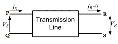
ABCD parameters (also known as chain or transmission line parameters) are generalized circuit constants used to help model transmission lines. More specifically, ABCD parameters are used in the two port network representation of a transmission line. The circuit of such a two-port network is shown below:

A major section of power system engineering deals in the transmission of electrical power from one place (eg. generating station) to another (e.g. substations or residential homes) with maximum efficiency.
So it’s important for power system engineers to be thorough with the mathematical modeling of how this power is transmitted. ABCD parameters and a two-port model is used to simplify these complex calculations.
To maintain the accuracy of this mathematical model, transmission lines are classified into three types: short transmission lines, medium transmission lines, and long transmission lines.
The formula for these ABCD parameters will change depending on the length of the transmission line. This is necessary since certain electrical phenomena – such as corona discharge and the Ferranti effect – only come into play when dealing with long transmission lines.
As the name suggests, a two-port network consists of an input port PQ and an output port RS. In any 4 terminal network, (i.e. linear, passive, bilateral network) the input voltage and input current can be expressed in terms of output voltage and output current. Each port has 2 terminals to connect itself to the external circuit. Thus it is essentially a 2 port or a 4 terminal circuit, having:
![]() Given to the input port PQ.
Given to the input port PQ.![]() Given to the output port RS.
Given to the output port RS.
Now the ABCD parameters of the transmission line provide the link between the supply and receiving end voltages and currents, considering the circuit elements to be linear in nature.
Thus the relation between the sending and receiving end specifications is given using ABCD parameters by the equations below.![]()
Now in order to determine the ABCD parameters of the transmission line let us impose the required circuit conditions in different cases.
The receiving end is open-circuited meaning the receiving end current IR = 0.
Applying this condition to equation (1) we get,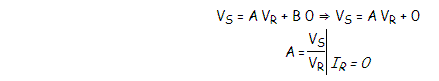
Thus it’s implied that on applying open circuit condition to ABCD parameters, we get parameter A as the ratio of sending end voltage to the open circuit receiving end voltage. Since dimension-wise A is a ratio of voltage to voltage, A is a dimensionless parameter.
Applying the same open circuit condition i.e IR = 0 to equation (2)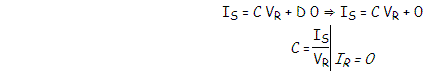
Thus it’s implied that on applying open circuit condition to ABCD parameters of a transmission line, we get parameter C as the ratio of sending end current to the open circuit receiving end voltage. Since dimension wise C is a ratio of current to voltage, its unit is mho.
Thus C is the open circuit conductance and is given by
C = IS ⁄ VR mho.
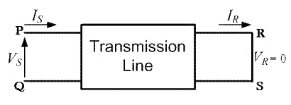
Receiving end is short circuited meaning receiving end voltage VR = 0
Applying this condition to equation (1) we get,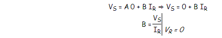 Thus it’s implied that on applying short circuit condition to ABCD parameters, we get parameter B as the ratio of sending end voltage to the short circuit receiving end’s current. Since dimension wise B is a ratio of voltage to current, its unit is Ω. Thus B is the short circuit resistance and is given by
B = VS ⁄ IR Ω.
Applying the same short circuit condition i.e VR = 0 to equation (2) we get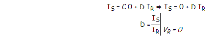 Thus it’s implied that on applying short circuit condition to ABCD parameters, we get parameter D as the ratio of sending end current to the short circuit receiving end current. Since dimension wise D is a ratio of current to current, it’s a dimensionless parameter.
∴ The ABCD parameters of the transmission line can be tabulated as:
Parameter |
Specification |
Unit |
A = VS / VR |
Voltage ratio |
Unit less |
B = VS / IR |
Short circuit resistance |
Ω |
C = IS / VR |
Open circuit conductance |
mho |
D = IS / IR |
Current ratio |
Unit less |
Statement: Respect the original, good articles worth sharing, if there is infringement please contact delete.


