
Plugging (Reverse Current Braking) in DC Motors
In plugging (reverse current braking), the armature terminals or supply polarity of a separately excited or shunt motor is reversed while the motor is running. This causes the supply voltage V and the induced back EMF Eb to act in the same direction. Consequently, the effective voltage across the armature during plugging becomes V + Eb—nearly double the supply voltage—reversing the armature current and generating high braking torque. An external current-limiting resistor is connected in series with the armature to restrict the current to a safe level.
The connection diagram and characteristics of a DC separately excited motor during plugging are illustrated in the figure below:
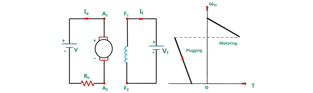
Notation:
V: Supply voltage
Rb: External braking resistance
Ia: Armature current
If: Field current
The connection diagram and operational characteristics of a series motor during plugging are shown in the figure below:
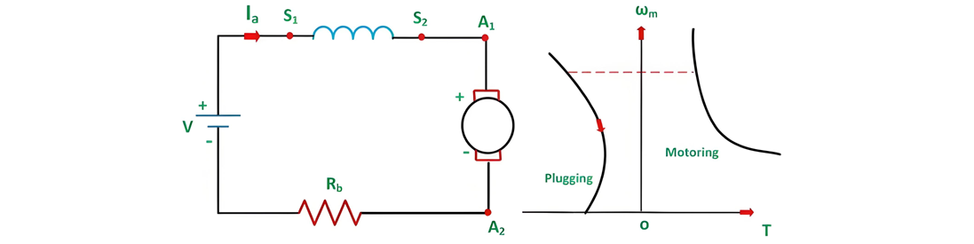
Plugging Braking Principles and Considerations
For series motors, plugging braking is achieved by reversing either armature terminals or field terminals—but not both simultaneously, as reversing both results in normal operation.
Notably, braking torque does not vanish at zero speed. To stop a load, the motor must be disconnected from the supply at or near zero speed; otherwise, it will accelerate in the reverse direction. Centrifugal switches are typically used for this disconnection.
Plugging (reverse current braking) is inherently inefficient: in addition to dissipating power from the load, it wastes source-supplied power in the braking resistors.
Applications of Plugging Braking
Common uses include:


