1. Significance of Enhancing Fault Handling for 220 kV Outgoing Circuit Breakers and Disconnectors
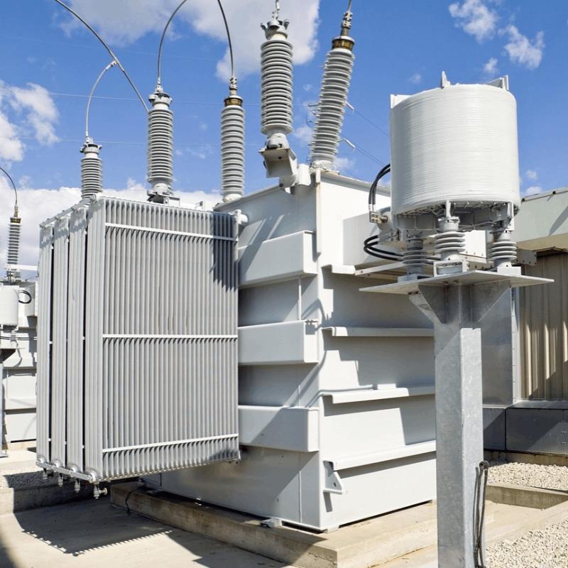
220 kV transmission lines are highly efficient and energy-saving high-voltage power transmission systems that significantly benefit daily life. A fault in a circuit breaker can severely compromise the safety and reliability of the entire power grid. As critical components of high-voltage transmission systems, circuit breakers and disconnectors play essential roles in power flow control and fault protection, effectively safeguarding both personnel and the power system.
With the rapid increase in transmission loads and the rising frequency of short-circuit faults, electrical safety incidents may occur, potentially causing circuit breakers to operate under overload conditions. While circuit breakers are designed to automatically interrupt the circuit during faults to protect equipment, their performance can be affected by factors such as the switchgear itself, control systems, and external non-equipment-related influences—leading to operational deviations. Therefore, strengthening fault diagnosis and handling for 220 kV outgoing circuit breakers and disconnectors is of critical importance.
2. Maintenance of 220 kV Outgoing Circuit Breakers and Disconnectors
2.1 Line Maintenance
During routine line maintenance operations, personnel must carefully observe for any abnormal phenomena. For example, after opening a circuit breaker, unusual discharge sounds should be noted. Any anomalies must be immediately reported to the relevant safety department. Only after passing inspection and verification should further operations proceed.
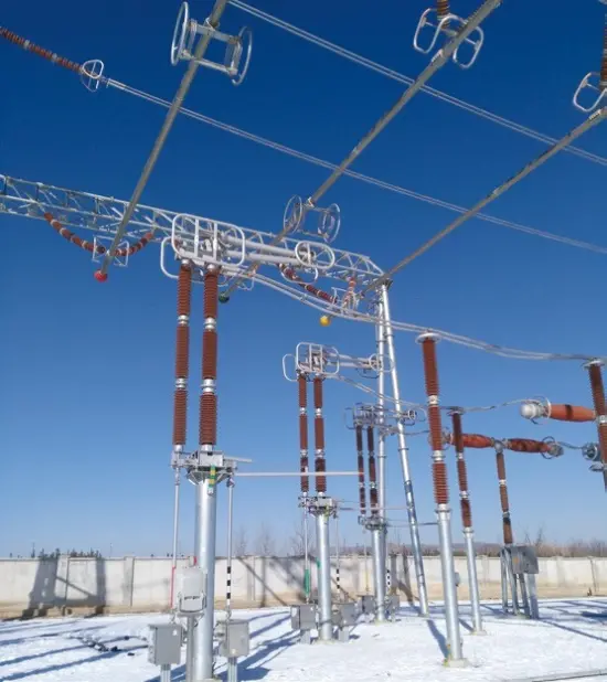
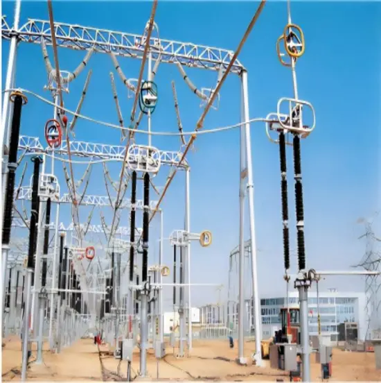
Each outgoing feeder and power branch typically passes through one circuit breaker and two sets of busbar disconnectors before connecting to two separate busbars. This configuration significantly enhances the reliability and flexibility of busbar operation and offers the following advantages:
Each busbar can be maintained alternately without interrupting normal power supply.
Maintenance of a disconnector on one busbar side affects only that specific circuit.
In the event of a failure on the operating busbar, load can be transferred to the alternate busbar to ensure uninterrupted power delivery.
2.2 Anti-Misoperation Checks for Circuit Breakers and Disconnectors
During installation, circuit breakers and disconnectors are susceptible to various external influences. Improper operation may cause unintended short circuits between disconnectors, grounding switches, and circuit breakers, leading to malfunctions in electrical or electromagnetic interlocking devices.
To minimize such risks, maintenance personnel must strictly adhere to standardized installation procedures. If a misoperation occurs, the positions of the circuit breaker and disconnector must be immediately verified. Only after confirming correct alignment should subsequent work continue.
Additionally, to prevent energized-load switching of disconnectors during maintenance, the disconnector’s control circuit must be interlocked with its associated circuit breaker. Should the interlock fail—or if the disconnector or grounding switch malfunctions—personnel must inspect the positions of the circuit breaker and disconnector according to interlock protocols. The lock may only be released after confirming everything is correctly positioned.
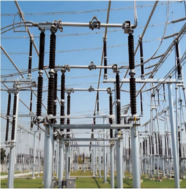
2.3 Overheating Contact Repairs
If overheating is detected at disconnector contacts, corrective actions should be taken after de-energizing the equipment. Addressing overheating on the busbar-side disconnector typically requires a busbar outage, which is often difficult to schedule. Hence, proactive routine inspections of busbar-side disconnectors are essential.
When maintaining line-side disconnectors, technicians should pay attention to the following key points:
Inspect the terminal connectors on the operating side of the disconnector. Ensure they use iron-alloy brazed clamps, high-quality forged nuts, and secure fastening hardware. The contact surfaces should be polished clean of contaminants and evenly coated with an appropriate conductive grease.
Examine the rotating copper strap at the disconnector base. Check for looseness or excessive wear on the copper strap inside the operating mechanism housing. Replace any damaged copper straps and re-secure them to ensure reliable electrical connection.
Inspect the static and dynamic contact surfaces to ensure they are clean and smooth. Replace worn contact fingers or degraded contact surfaces promptly to prevent partial discharge or flashover. Additionally, verify that the clamping spring assembly provides sufficient pressure; replace or tighten any corroded or loose components.
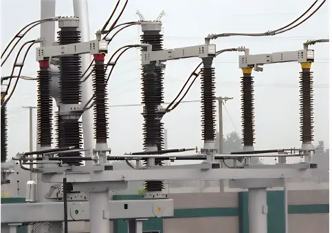
2.4 Maintenance for Insulator Damage and Flashover
If insulator cracking or flashover discharge is observed on a disconnector, the following steps should be taken:
First, use an ultrasonic non-destructive testing (NDT) instrument to inspect the porcelain column and confirm there is no internal damage to the current-carrying conductor. Only after passing this inspection should the unit remain in service.
Second, maintain the disconnector insulators properly. If NDT reveals no defects, apply a non-insulating protective coating to the crimped area of the porcelain column.
Third, to enhance pollution-flashover resistance, prioritize the use of anti-pollution insulators and increase both the height and creepage distance of the porcelain columns.
3. Application of GPRS Wireless Communication in Highway Electromechanical Systems
Effectively addressing the above challenges does not require laying dedicated communication cables. Instead, a mobile network IP address can be configured to establish direct connectivity with field devices. Moreover, GPRS technology is not constrained by distance and can transmit complex data economically and efficiently.
The central monitoring system serves as the core of the overall surveillance architecture. It receives and processes data collected from field devices, enabling optimized control strategies and remote management of field equipment. This system typically integrates cameras, video surveillance units, computers, and related hardware.
3.2 Technical Advantages of GPRS in Toll Collection Systems
Prior to adopting GPRS, toll plazas and control centers on expressways relied on wired communication systems for data transmission. These systems proved inefficient, required substantial upfront investment, and incurred high maintenance costs.
With GPRS, no physical conduits or cabling are needed—communication is possible anywhere within mobile network coverage. GPRS systems demonstrate high stability in operation, integrate multiple communication protocols, and offer significantly improved efficiency compared to traditional wired solutions. Furthermore, GPRS supports diverse service types and is particularly well-suited for point-to-point broadband wireless access in areas with high bandwidth demands or remote locations. Its reliance on existing mobile infrastructure eliminates the need for trenching or conduit installation, offering substantial technical and economic advantages.
3.3 Technical Advantages of GPRS in Communication Systems
In highway communication systems, GPRS offers numerous benefits. Highway authorities regularly deploy patrol vehicles for routine inspections and incident response. Since accident locations are unpredictable, real-time reporting of road conditions to the monitoring center requires reliable wireless communication. For applications with moderate data rate requirements, GPRS provides an ideal solution for data transmission.
The patrol vehicle dispatch system consists of onboard equipment and a central monitoring platform. Using GPRS, the onboard unit acquires real-time vehicle location data and transmits it to the monitoring center, enabling centralized tracking of all patrol vehicles. This ensures rapid response to emergencies. Upon receiving vehicle status updates, the monitoring center can send command instructions via a GIS platform to the onboard terminal, facilitating efficient coordination and on-site operations.
4. Conclusion
Continuous advancements in science and technology have driven significant progress in communications, internet, and information technologies. The integration of GPRS wireless communication into highway electromechanical systems has substantially enhanced expressway management capabilities. GPRS demonstrates compelling technical advantages across monitoring, toll collection, and communication subsystems. Therefore, wider adoption of GPRS technology in highway electromechanical infrastructure will effectively support the sustainable development and intelligent operation of modern expressway networks.