• Product
  • Suppliers
  • Manufacturers
  • Solutions
  • Free tools
  • Knowledges
  • Experts
  • Communities
Search


Zirkuito RLC analisia (seriekoa eta paraleloa)

Electrical4u
Electrical4u
Eremua: Elektrizitate Oinarrizko
0
China

In an RLC circuit, the most fundamental elements of a resistor, inductor, and capacitor are connected across a voltage supply. All of these elements are linear and passive in nature. Passive components are ones that consume energy rather than producing it; linear elements are those which have a linear relationship between voltage and current.

There are number of ways of connecting these elements across voltage supply, but the most common method is to connect these elements either in series or in parallel. The RLC circuit exhibits the property of resonance in same way as LC circuit exhibits, but in this circuit the oscillation dies out quickly as compared to LC circuit due to the presence of resistor in the circuit.

When a resistor, inductor and capacitor are connected in series with the voltage supply, the circuit so formed is called series RLC circuit.

Since all these components are connected in series, the current in each element remains the same,


Let VR be the voltage across resistor, R.
VL be the voltage across
inductor, L.
VC be the voltage across
capacitor, C.
XL be the inductive
reactance.
XC be the capacitive reactance.
rlc circuit
The total voltage in the RLC circuit is not equal to the algebraic sum of voltages across the resistor, the inductor, and the capacitor; but it is a vector sum because, in the case of the resistor the voltage is in-phase with the current, for inductor the voltage leads the current by 90o and for capacitor, the voltage lags behind the current by 90o (as per ELI the ICE Man).

So, voltages in each component are not in phase with each other; so they cannot be added arithmetically. The figure below shows the phasor diagram of the series RLC circuit. For drawing the phasor diagram for RLC series circuit, the current is taken as reference because, in series circuit the current in each element remains the same and the corresponding voltage vectors for each component are drawn in reference to common current vector.

vector diagram of rlc circuit

The Impedance for a Series RLC Circuit

vector diagram of rlc circuit
The impedance Z of a series RLC circuit is defined as opposition to the flow of current due circuit resistance R, inductive reactance, XL and capacitive reactance, XC. If the inductive reactance is greater than the capacitive reactance i.e XL > XC, then the RLC circuit has lagging phase angle and if the capacitive reactance is greater than the inductive reactance i.e XC > XL then, the RLC circuit have leading phase angle and if both inductive and capacitive are same i.e XL = XC then circuit will behave as purely resistive circuit.
We know that

Where,
Substituting the values

Parallel RLC Circuit

In parallel RLC Circuit the resistor, inductor and capacitor are connected in parallel across a voltage supply. The parallel RLC circuit is exactly opposite to the series RLC circuit. The applied voltage remains the same across all components and the supply current gets divided.

The total current drawn from the supply is not equal to mathematical sum of the current flowing in the individual component, but it is equal to its vector sum of all the currents, as the current flowing in resistor, inductor and capacitor are not in the same phase with each other; so they cannot be added arithmetically.
parallel rlc circuit
Phasor diagram of parallel RLC circuit, IR is the current flowing in the resistor, R in amps.
IC is the current flowing in the capacitor, C in amps.
I

Ordaintza ematea eta egilea bermatzea
Gomendioa
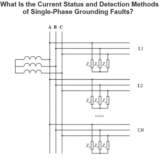
Zein da Uneko Egoera eta Detektatze Moduak Monofaseko Lurraje Akatsentzat?
Unekoan erdigintza akatsen detektatzeko egoeraErdigintza-akatsen diagnostrizaren zehaztasuna txikia denean, ez dituen erdigintza sistemetan hainbat faktore daude: banaketa saretako egitura aldakorra (hala nola, mugagabe eta mugatua), sistema erdigintza modu anitzak (gabonetako, arkuzuriarekin gabonetako eta erresistentzia baxuko gabonetako), urteko kable edo kable eta airean idazketa konbinatuaren maila handiagoa, eta akats mota konplexuak (hala nola, ozarre-sarrerak, zuhaitz-egunaldiak, harateg
Leon
08/01/2025
Maiztasunezko metodoa sarearen eta lurren arteko izolamendu-parametroen neurrirako
Frekuentzia-banaketaren metodoak sakonpuntura-lerroetatik lurreko parametroen neurketa ahalbidetzen du potentzia-transformator (PT)ren delta irekian frekuentzia desberdina duen korronte bat inprimatzea bidez.Metodo hau erabil daiteke zati-sakontasunezko sistemetan; baina, sistema baten sakonpuntura-lerroetatik lurreko parametroak neurtzerakoan, non neurri-puntu neutroa arkuen supresio koil batez sakontasunez konektatuta dago, arkuen supresio koila lehendik kendu behar da. Neurrirako oinarrizko p
Leon
07/25/2025
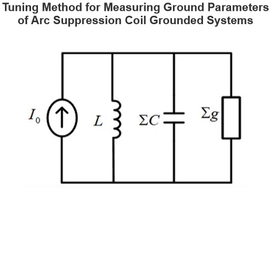
Arikotasuneko arku supresio koilu oinarritutako sistemaren lurreko parametroak neurtzeko doinu metodoa
Ajuste metodoa oso ondo doitu da neurrizko parametroak neurriz, sistema batean non neurri-puntu neutroa arkua kendu duen koilu bidez lotuta dagoela, baina ez da aplikagarria neurri-puntu neutroa lotu gabeko sistemetarako. Neurketa printzipioak kontinuoki aldatzen den maiztasuneko korronte bat sartzea Potentzial Transformadorearen (PT) bigarren aldetik, itzultutako tentsio-sinala neurtzea eta sistemaren erresonantzi-frekuentzia identifikatzea dakar.Maiztasun barraskatuaren prozesuan, sartutako ka
Leon
07/25/2025
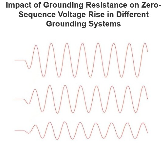
Lurraldeko erresistentziaren eragina nulu-zerrendako tentsio-igoera desberdinetan egituratutako lurratzeko sistemetan
Arkudun supresio koila oinarritutako sisteman, zeroko ordena geruzaren goraketa abiadura oso handitan eragiten du lotura puntuaren iturri mugikortasun balioa. Lotura puntuaren iturri mugikortasuna gehiago, zeroko ordena geruzaren goraketa abiadura motzenagoa izango da.Loturik gabeko sisteman, lotura puntuaren iturri mugikortasunak ez du praktikan eraginik zeroko ordena geruzaren goraketa abiaduran.Simulazio Analisia: Arkudun supresio koila oinarritutako sistemaArkudun supresio koila oinarritutak
Leon
07/24/2025
Eskaera bidali
Jeitsi
IEE Business aplikazioa lortu
IEE-Business aplikazioa erabili ekipamendua bilatzeko, soluzioak lortzeko, adituekin konektatzeko eta industria lankidetzan parte hartzeko edonon eta edonoiz — zure energia proiektu eta negozioen garapenerako laguntza osoa ematen du.