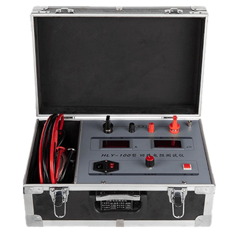
HLY-100 Circuit Resistance Tester Application Solution

I.Application Scenarios & Core Requirements
The HLY-100 Circuit Resistance Tester, developed based on standards GB-74 and IEEE 694-84, integrates a DC high-current source, a digital ammeter, and an ohmmeter. It is tailored for the following three core scenarios, precisely meeting different user testing needs:
|
Application Scenario |
Core Requirement |
Pain Points of Traditional Solutions |
|
Power System Maintenance (Substations, Distribution Rooms, etc.) |
Periodically test the contact resistance of high-voltage switches, disconnectors, etc., to prevent overheating and burnout faults caused by poor contact, ensuring grid stability. |
1. Small test current (mostly below 10A), failing to simulate actual operating conditions, resulting in low data relevance. |
|
Industrial Electrical Equipment Acceptance (Factory Motors, Distribution Cabinets, etc.) |
Verify that the circuit resistance of current-carrying paths (e.g., cable joints, contactor contacts) meets design standards after new installation or major overhaul, preventing safety incidents caused by excessive resistance after commissioning. |
1. Lack of integrated test equipment, requiring separate configuration of current source, ammeter, and ohmmeter, resulting in cumbersome operation and complex wiring. |
|
Electrical Equipment Production Quality Inspection (Switches, Cable Manufacturers, etc.) |
Perform batch testing of circuit resistance for finished products, ensuring quality compliance and adherence to industry delivery standards. |
1. Low measurement efficiency of traditional instruments, struggling to meet rapid quality inspection needs for mass production. |
II. Core Technology & Advantages
(A) Core Technological Support
- AC-DC Switching Power Supply Technology: Capable of stably outputting a high test current of 100A, accurately simulating the actual current conditions of electrical equipment operation. This helps avoid missing contact resistance hazards that "low-current testing" might overlook, ensuring measurement results reflect the true operating state of the equipment.
- Four-Terminal Measurement Method: Completely separates the "current loop" from the "voltage measurement loop," effectively eliminating interference from test lead resistance and terminal contact resistance on measurement results. Significantly improves data accuracy, with measurement precision up to 1%, far superior to the traditional two-terminal method.
- Integrated Design: Integrates three functional modules - a DC high-current source, a digital ammeter, and an ohmmeter - into a single unit. No need for additional equipment, simplifying wiring processes and operation steps, and reducing the skill threshold for operators.
(B) Core Solution Advantages
- Accuracy: 100A rated output current + 1% measurement precision meets the stringent requirements of standards like GB-74 and IEEE 694-84 for electrical equipment circuit resistance testing. Data can be directly used as a basis for equipment acceptance and maintenance decisions.
- Convenience: Compact structure and strong portability suit scenarios like substation inspection and mobile testing in factory workshops. Operates on 220V single-phase three-wire power input, requiring no special power configuration; can be plugged into standard mains on-site.
- Environmental Adaptability: Wide operating temperature range of -10°C to 50°C, allowing stable operation in complex environments like cold substations or hot industrial workshops, avoiding measurement errors or equipment failures due to ambient temperature fluctuations.
- Full Lifecycle Support: The supplier provides full lifecycle management services covering "procurement - use - maintenance - after-sales," assigns a dedicated support manager, and guarantees a response time of ≤4 hours for equipment failures, ensuring testing continuity and reducing user maintenance costs.
III. Specific Application Implementation Process
(A) Implementation Steps for Power System Maintenance Scenario
- Preparation: Confirm the equipment to be tested (e.g., high-voltage disconnector, circuit breaker) is de-energized and grounded. Clean oxidation and dirt from the equipment's terminal surfaces to ensure good contact. Bring the HLY-100 tester and matching test leads (red and black, two sets of four-terminal leads) to the site.
- Equipment Connection: Wire according to the "four-terminal measurement method" – connect the tester's "Current Output Positive/Negative" terminals to the two ends of the device's circuit under test (main circuit). Connect the "Voltage Measurement Positive/Negative" terminals to both ends of the device's contacts under test (precise measurement points near the contacts), avoiding bridging the test lead resistance.
- Parameter Setting & Testing: Connect the tester to a 220V mains power source. After powering on, the default output is 100A test current (no manual adjustment needed). Press the "Start Test" button; the instrument automatically applies the current, measures the voltage, and calculates and displays the circuit resistance value in real-time (unit: μΩ, range 0~1999μΩ). Data is automatically saved upon test completion.
- Data Judgment & Recording: Compare the test data with equipment maintenance standards (e.g., contact resistance for high-voltage switches is typically required to be ≤100μΩ). If data exceeds the standard, mark the equipment promptly and schedule maintenance. Upload test data to the maintenance management system to build equipment health records.
(B) Implementation Steps for Industrial Equipment Acceptance Scenario
- Acceptance Standard Confirmation: Define the acceptable circuit resistance threshold based on equipment design drawings or industry standards (e.g., resistance requirement for motor cable joints ≤50μΩ).
- On-site Testing: After new equipment installation is complete, disconnect the main power supply. Connect the tester using the "four-terminal wiring" method described above, initiate the test, and record the data. For drawer-type distribution cabinets, test the contacts of the contactors and circuit breakers directly within the cabinet.
- Acceptance Conclusion: If the test data falls within the acceptable range, issue an acceptance certificate. If the data exceeds the standard, assist the installation team in troubleshooting (e.g., loose connections, oxidized terminals), retest after rectification until standards are met.
(C) Implementation Steps for Production Quality Inspection Scenario
- Production Line Adaptation: Set up a fixed test station at the end of the production line, equipped with the HLY-100 tester and automated connection jigs (custom rapid-connection fixtures can be made for batch products) to reduce manual wiring time.
- Batch Testing: Each finished product (e.g., low-voltage switch) is conveyed to the test station. Manual/robotic arms complete the four-terminal connection. Initiate the tester; a single test is completed within 3-5 seconds. The system automatically determines "Pass/Fail" with audio-visual alarms. Failed products are automatically diverted to the rework area.
- Data Traceability: Connect the tester to the Manufacturing Execution System (MES) to automatically record test time, resistance value, operator, etc., for each product, creating traceable quality inspection records that meet industry quality control requirements.
IV. Solution Value & Support
(A) Customer Value
- Safety Assurance: Prevents localized overheating, burnout, and even fire accidents caused by excessive resistance during equipment operation through accurate detection of contact resistance hazards, safeguarding personnel and equipment.
- Efficiency Improvement: Integrated design and convenient operation reduce testing time per device to under 5 minutes (compared to 15-20 minutes for traditional solutions), significantly boosting maintenance and quality inspection efficiency.
- Cost Savings: Full lifecycle after-sales support reduces equipment repair costs. Early detection of potential faults avoids losses from downtime (e.g., daily losses from factory motor failure downtime can reach tens of thousands).
(B) Supplier Support
- Service Response: Commitment to ≤4 hour service response, 7x24 technical support. A backup unit can be provided in case of equipment failure to avoid testing interruptions.
- Customization Support: For special requirements (e.g., higher current needs, automated test integration), customized technical solutions can be provided to adapt to user-specific needs.