The 8-Phase Guide to Installing LW25-126 High-Voltage Circuit Breakers Correctly

1. Pre-Installation Preparations
Before commencing installation work, the following preparatory steps must be completed:
Organization and Training: Organize training sessions for all construction personnel on relevant regulations,technical standards, and construction procedures. Special emphasis should be placed on safety protocols.
Site Survey: Examine the intended location of the circuit breaker, its foundation, and the layout of surrounding equipment and wiring to prevent accidental contact with energized equipment during installation.
Preparation of Tools and Materials:Position specialized tools and required materials near the work site and implement protective measures against rain. Maintain a detailed checklist of all tools and materials, including types and quantities.
2. Common Issues During Installation and Corresponding Solutions
Prior to beginning installation, conduct the following additional inspections:
Inspect Internal Components: Check that all internal components (e.g., relays) within the operating mechanism are complete and undamaged. Pay particular attention to insulating parts, ensuring their surfaces are free from cracks or damage.
Inspect Porcelain Bushings: Examine porcelain bushings for smoothness and absence of cracks. If in doubt, request non-destructive testing (NDT). Also verify the strength and integrity of the bond between the bushing and flange.
Inspect Component Materials:Confirm the availability and condition of bolts, sealing gaskets, sealing grease, lubricating grease, and other auxiliary materials.
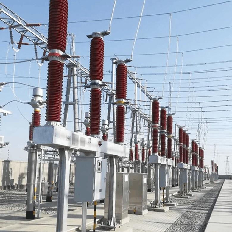
Support Structure Installation
Use cranes for lifting, with one signalman assigned per crane.
Crane operators and signalmen must take care to avoid contact between the crane boom and overhead busbars or electrical equipment in adjacent bays.
All other personnel have the responsibility to warn against and prevent accidental contact.
No more than three shims should be used between the support and foundation, with a total thickness not exceeding 10 mm.
Crossbeam and Operating Mechanism Installation
The crossbeam and operating mechanism form a single unit. Use two lifting slings during hoisting—one attached to the crossbeam and the other to the operating mechanism—to prevent imbalance.
After installation, verify that the crossbeam is level and meets specified tolerances.
Main Pole Column Installation
Ensure the flange surfaces of the three-phase porcelain bushings are aligned on the same horizontal plane.
The deviation in center-to-center distance between each pole column should not exceed 5 mm.
Use a torque wrench to tighten the bolts connecting the pole column to the crossbeam, ensuring torque values comply with the manufacturer’s specifications.
Connecting Linkages, Secondary Wiring, Primary Leads, and SF6 Piping
Linkage Connections
Sequence: First connect the linkage between the pole column and the operating mechanism, then connect the linkages between pole columns.
Apply a mixture of engine oil and molybdenum disulfide lubricant to the pin joints to ensure smooth operation.
Secondary Control Wiring
Ensure correct wiring with no loose or false connections.
Each secondary wire must be fitted with a clearly and accurately labeled wire marker to facilitate future troubleshooting.
Primary Lead Connections
Ensure contact surfaces of the terminal clamps are flat and clean.
If oxidation is present, polish the surface with sandpaper. For silver-plated surfaces, use the backside of the sandpaper to avoid damaging the plating.
Apply a uniform layer of electrical compound grease after cleaning, with a thickness of no less than 1 mm.
When inserting bolts, orient the bolt head downward and the nut upward (to facilitate detection of loosening).
Tighten bolts diagonally in sequence to ensure even pressure distribution.
SF6 Gas Piping Connections
Ensure all joints are tightly sealed. Use PTFE (Teflon) tape as a secondary sealant on threaded connections if necessary.
Gas Charging Procedure
After connecting the charging equipment, slightly open the gas cylinder valve to purge air from the charging hose for approximately 3 minutes, ensuring the hose is free of contaminants.
Wipe the circuit breaker’s gas inlet port with a lint-free cloth dampened with anhydrous alcohol until completely clean and dust-free.
Charge the gas slowly to prevent frost formation on the cylinder or piping.
Fill to the rated pressure of 0.5 MPa.
3. Testing and Inspection
After installation, perform the following tests to verify work quality:
DC Resistance Test
With the circuit breaker in the closed position, perform the test phase by phase (A, B, C).
Requirement: DC resistance of each phase must be less than 40 µΩ.
Mechanical Characteristic Test
The following tests and reference values are required (see Table 1):
Table 1. Reference Values for Mechanical Characteristics of LW25-126 Circuit Breaker
Test Item |
Standard Value |
Opening Time |
≤ 30 ms |
Closing Time |
≤ 150 ms |
Opening Synchronization |
≤ 2 ms |
Closing Synchronization |
≤ 4 ms |
Minimum Voltage for Opening |
≥ 66 V and ≤ 143 V |
Minimum Voltage for Closing |
≥ 66 V and ≤ 143 V |
Moisture (Micro Water) Test
Conduct the test at least 24 hours after gas charging.
Requirement: Moisture content in the arc extinguishing chamber must not exceed 150 µL/L.