Optimization of Grounding Methods for Power Transformer Core and Clamps

Transformer grounding protection measures are divided into two types: The first is transformer neutral point grounding. This protection measure prevents neutral point voltage drift caused by three-phase load imbalance during transformer operation, enabling protection devices to trip quickly and reducing short-circuit currents. This is considered functional grounding for the transformer. The second measure is grounding of the transformer core and clamps.
This protection prevents induced voltages from developing on the core and clamp surfaces due to internal magnetic fields during operation, which could lead to partial discharge faults. This is considered protective grounding for the transformer. To ensure safe and reliable transformer operation, this article analyzes and optimizes grounding methods specifically for transformer cores and clamps.
1.Importance of Core and Clamp Grounding
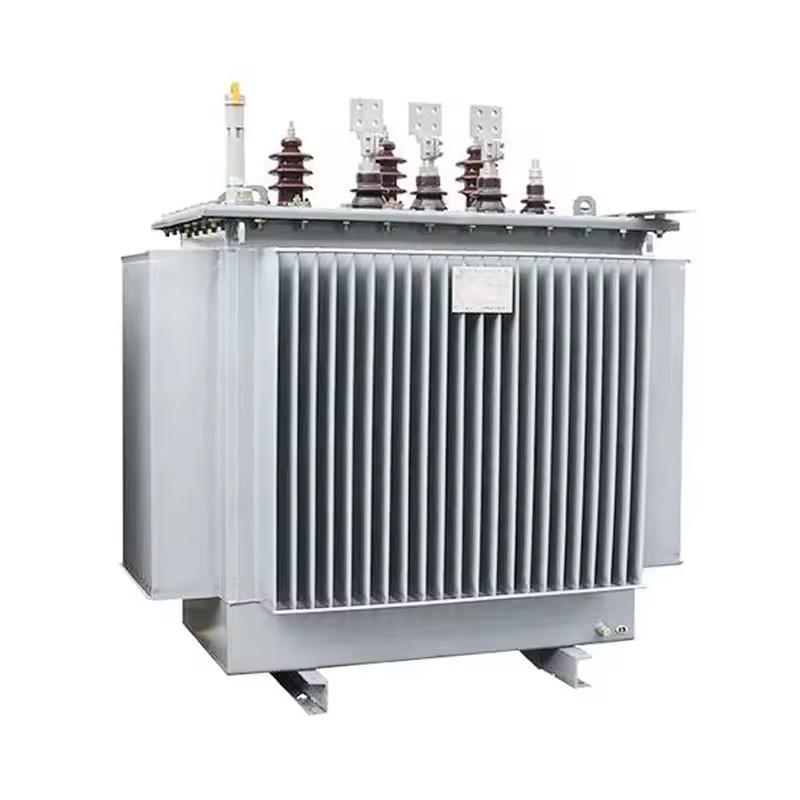
The main internal components of a transformer include: windings, core, and clamps. Windings form the electrical circuit of the transformer, the core constitutes the magnetic circuit, and clamps are primarily used to secure the windings and silicon steel sheets of the core. During normal operation, primary and secondary coils generate magnetic fields when current flows through them. Under this magnetic environment, induced voltages develop on the surfaces of the core and clamps.
As magnetic field strength increases, magnetic flux gradually grows larger, causing induced voltages to rise progressively. Due to uneven magnetic field distribution, non-uniform induced voltages create potential differences, resulting in continuous discharge on the core and clamp surfaces, leading to internal transformer faults. This voltage causing internal discharge faults in transformers is called "floating voltage." Therefore, during operation, the transformer core and clamps must be grounded at a single point to reduce and eliminate induced voltages.
When grounding the transformer core and clamps, only one grounding point is permitted to prevent circulating currents between the core and clamps. If two or more grounding points exist, potential differences will cause circulating currents between the core and clamps, leading to abnormal temperature increases inside the transformer. This directly damages internal solid insulation and accelerates insulation oil aging, affecting the normal service life of the transformer.
2. Grounding Methods for Core and Clamps and Optimization Approaches
In China's current transformer designs, core and clamp grounding is primarily achieved by routing connections through small bushings or insulated bolts to the transformer tank exterior before grounding. This grounding approach is further divided into two methods:
The first grounding method (Figure 1) connects the core and clamps through bushings or insulated bolts, then directly short-circuits them together before grounding. During normal transformer operation, this grounding method exhibits three current flow paths, labeled I1, I2, and I3:
I1: Core → Grounding terminal → Ground
I2: Clamps → Grounding terminal → Ground
I3: Core → Grounding terminal → Ground → Clamps
The second grounding method (Figure 2) routes the core and clamps through bushings or insulated bolts to separate grounding points. This grounding method also exhibits three current flow paths during normal operation:
I1: Core → Core grounding point → Ground
I2: Clamps → Clamp grounding point → Ground
I3: Core → Core grounding point → Earth → Clamp grounding point → Clamps

Of the two grounding methods mentioned above, the induced grounding currents I1 and I2 represent normal conditions. However, the induced grounding current I3 differs significantly:
In the grounding method shown in Figure 1, the induced current flows through the path: core → grounding terminal → clamps, creating a "circulating current" between the transformer core and clamps. Under the thermal effect of this current, the internal temperature of the transformer abnormally increases. High temperature directly causes solid insulation degradation and insulation oil aging. Additionally, due to the influence of circulating current, online monitoring systems cannot accurately measure the grounding currents of the core and clamps, leading to misdiagnosis when equipment faults occur. Therefore, the first grounding method has significant drawbacks.
In contrast, the grounding method shown in Figure 2 routes the induced current through: core → core ground → earth → clamp ground → clamps. Since the current passes through high-resistance earth, no "circulating current" can form between the core and clamps. This prevents abnormal temperature rise in the transformer and allows online monitoring systems to precisely measure the grounding currents of both core and clamps (according to DL/T 596-2021 Power Preventive Test Code, the core grounding current must not exceed 0.1 A and clamp grounding current must not exceed 0.3 A during transformer operation). This provides reliable evidence for determining whether internal faults exist within the transformer.
For the xx-223000/500 no-excitation voltage regulating power transformer, the core and clamps are grounded using the method shown in Figure 1, which presents several operational issues:
(1) During operation, a "circulating current" easily forms between the internal core and clamps. The thermal effect causes abnormal temperature increases, accelerating solid insulation degradation and insulation oil aging, thereby reducing the transformer's service life.
(2) Due to the influence of "circulating current," online monitoring systems cannot accurately measure the grounding currents of the core and clamps, making it impossible to provide conclusive evidence for determining internal faults.
(3) The induced grounding currents of the core and clamps can be continuously measured and compared with leakage currents monitored by the online system to verify the monitoring system's accuracy.
(4) During transformer maintenance and repair, when measuring insulation resistance between core/clamps and ground, external grounding leads must be disconnected. Since this transformer model uses M10 copper bolts (insulated from ground) for core and clamp connections, which have excellent conductivity but low mechanical strength and are prone to breakage. During field operations, confined spaces and unbalanced forces can easily cause copper bolt fractures. Given the transformer's compact internal structure, addressing this fault requires lifting the tank cover for replacement, affecting normal maintenance cycles and operational efficiency.
Considering these four issues, to ensure accurate detection of core and clamp induced grounding currents during operation, extend transformer service life, eliminate "circulating currents," and prevent maintenance operations from causing damage that expands repair scope, it is recommended to optimize the transformer's core and clamp grounding method from the Figure 1 configuration to the Figure 2 configuration.
3.Conclusion
Through detailed introduction of transformer internal components and functions, along with scientific analysis of discharge faults occurring during operation, modifications to defective parts have been successfully implemented. This approach achieves extended equipment service life, improved power grid safety, and reduced equipment maintenance costs.