Analysis of Diagnostic Methods for Core Grounding Faults in 35 kV Distribution Transformers

35 kV Distribution Transformers: Core Grounding Fault Analysis and Diagnostic Methods
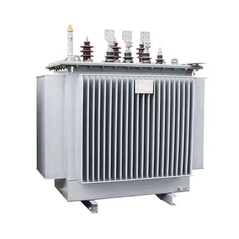
35 kV distribution transformers are common critical equipment in power systems, carrying important electrical energy transmission tasks. However, during long-term operation, core grounding faults have become a major issue affecting the stable operation of transformers. Core grounding faults not only impact transformer energy efficiency and increase system maintenance costs, but may also trigger more serious electrical failures.
As power equipment ages, the frequency of core grounding faults gradually increases, requiring enhanced fault diagnosis and treatment in power equipment operation and maintenance. Although certain diagnostic methods currently exist, there are still technical bottlenecks such as low detection efficiency and difficult fault location. There is an urgent need to explore and apply more precise, sensitive fault diagnosis technologies to improve equipment operational reliability and ensure power system stability and security.
1 Analysis of Causes and Characteristics of Core Grounding Faults in 35 kV Distribution Transformers
1.1 Common Causes of Core Grounding Faults
In 35 kV distribution transformers, insulating materials are typically used between core laminations for isolation. However, during long-term operation, internal electric fields and temperature cause gradual aging of insulation materials, particularly under high-voltage and high-temperature environments where insulation performance deteriorates rapidly. As aging progresses, insulation resistance decreases, and insulation failure in partial areas can form multi-point grounding faults.
Transformers inevitably experience mechanical vibration during extended operation. Especially under conditions of significant load fluctuations, vibration can cause relative displacement of the core and core clamping components. Loose core clamps or damaged isolation materials may trigger grounding faults. Transformer core manufacturing defects are also important causes of core grounding faults. During manufacturing, if silicon steel sheets have burrs, uneven insulation coating, or insufficient core processing precision, local insulation damage may occur. Such defects are often concentrated in the grounding parts of the transformer. When the electric field distribution in the core is uneven, partial discharge can occur.
1.2 Electrical Characteristics and Hazards of Faults
The most direct electrical characteristic of core grounding faults is increased grounding current. After a grounding fault occurs, the grounding current typically exhibits current fluctuations with harmonic components, particularly in high-frequency regions above 50 Hz. When faults occur, the waveform of the grounding current often appears non-sinusoidal, with larger amplitudes of harmonic components.
Another typical characteristic of core grounding faults is partial discharge. After insulation material failure, the electric field concentrates in damaged areas, causing corona discharge and partial discharge phenomena. Partial discharge typically generates high-frequency current pulses with frequency ranges generally between 3-30 MHz. Current signals in this frequency band can be captured and analyzed using specialized high-frequency current transformers (HFCT).
Another electrical characteristic triggered by core grounding faults is the temperature rise effect. Due to eddy current losses at the fault point, local temperature increases. This temperature rise effect not only directly damages insulation materials but may also cause overheating in partial areas of the core.
1.3 Impact of Faults on Transformer Operation
Core grounding faults lead to increased grounding current, which in turn causes additional losses in the transformer core. Core losses primarily consist of eddy current losses and hysteresis losses. When grounding faults occur, uneven magnetic flux distribution inside the transformer significantly increases eddy current losses in certain areas. This not only reduces transformer energy efficiency but may also significantly increase operational costs. The increased core losses exacerbate transformer overheating, further affecting long-term stable operation.

Partial discharge and temperature rise effects caused by core grounding faults accelerate the aging of internal insulation materials in transformers. During insulation aging, the resistance of insulation layers gradually decreases, and electrical isolation capability progressively fails. When insulation completely fails, it may trigger local short circuits or more serious complete short circuit accidents.
Core grounding faults not only lead to decreased electrical performance but also affect the chemical composition of transformer oil. When the core grounds, partial discharge and overheating cause the internal oil temperature to rise, leading to changes in dissolved gas components in the oil, particularly abnormal increases in methane (CH4) and ethylene (C2H4) content.
2 Diagnostic Methods and Technical Comparison for Core Grounding Faults
2.1 Traditional Diagnostic Methods
The DC resistance method is one of the traditional diagnostic methods for core grounding faults, primarily judging fault existence by measuring the insulation resistance between the core and ground. This method applies DC voltage and measures the ratio of current to voltage to calculate insulation resistance. Ideally, the core's insulation resistance should remain at a high value; if resistance drops below a certain threshold, it may indicate a grounding fault.
However, the DC resistance method cannot accurately locate fault points. Its measurement results can only reflect the average insulation performance of the entire core and cannot determine specific fault areas. This method also has a certain lag, particularly when insulation aging has not yet caused significant resistance changes, making early fault detection ineffective. Additionally, the DC resistance method cannot provide information about fault types, and detailed fault characteristics cannot be effectively extracted from measurement data.
Oil chromatography analysis detects changes in dissolved gas components in transformer oil to infer fault types. These dissolved gases are typically produced when discharge, overheating, or other electrical failures occur inside the transformer. Common gas components in transformer oil include methane (CH4), ethylene (C2H4), ethane (C2H6), etc. Changes in gas concentrations can reflect the transformer's operational status.
By comparing dissolved gas concentrations in oil with fault types, it's possible to preliminarily determine whether a core grounding fault has occurred in the transformer. Oil chromatography analysis has a relatively delayed response; after a fault occurs, it takes time for dissolved gases to accumulate, limiting the timeliness of fault diagnosis. Furthermore, oil chromatography analysis cannot provide accurate fault locations or specific characteristics, only indicating faults through gas concentration changes. For minor or intermittent faults, oil chromatography analysis diagnosis may be delayed and unable to respond promptly to fault occurrence.
2.2 Modern Instrument Detection Technologies
Partial discharge detection technology is based on the principle of high-frequency current transformers (HFCT), capturing and analyzing discharge pulse signals caused by core grounding to diagnose faults. When core grounding faults occur, partial discharge generates high-frequency current pulses at insulation damage points. These current signals typically manifest as high-frequency noise or pulse signals with frequency ranges generally between 3-30 MHz.
By installing high-frequency current sensors on the transformer's grounding line, partial discharge signals can be captured in real-time. This technology can efficiently locate partial fault points, has high sensitivity, and can detect faults at early stages. Partial discharge detection can effectively identify minor faults caused by insulation aging or mechanical damage, providing accurate fault diagnosis information. By analyzing partial discharge signals, the severity and development trend of faults can be assessed, allowing for corresponding maintenance or preventive measures.
Infrared thermal imaging technology detects local temperature rise areas in the core using infrared thermal imagers to determine if grounding faults exist. After grounding faults occur in transformers, eddy current losses in local areas cause temperature increases, particularly significant temperature rises around fault points. Infrared thermal imaging technology can obtain real-time temperature distribution on the core surface and determine fault existence through temperature differences. Typically, when temperature differences exceed 10°C, focused investigation of that area is needed. The advantage of this technology lies in its ability to detect temperature changes without contact, with fast measurement speed, making it suitable for rapid on-site detection.
High-frequency current detection method employs Rogowski coils to measure high-frequency current changes in grounding lines, typically in the frequency range of 500 kHz to 2 MHz. These high-frequency currents are generated by discharge processes caused by core grounding faults. By detecting current signals in this frequency range, fault existence can be effectively identified. Compared to partial discharge detection technology, high-frequency current detection has higher sensitivity and can capture extremely weak fault signals. Using Rogowski coils for non-contact measurement not only simplifies installation but also improves measurement accuracy. This technology is particularly suitable for areas difficult to access directly and can perform online detection without damaging equipment.
3 Optimization of Fault Diagnosis Process and Case Analysis
3.1 Recommendations for Optimized Diagnostic Process
When diagnosing core grounding faults, the first step should be preliminary screening using infrared thermal imaging technology. Infrared thermal imagers can quickly obtain temperature distribution maps of the transformer surface, helping diagnostic personnel identify possible abnormal temperature rise areas. Once preliminary screening identifies potential fault areas, the next step should combine high-frequency current detection and partial discharge detection technologies for precise testing.
The high-frequency current detection method captures grounding current changes in the 500 kHz to 2 MHz frequency band using Rogowski coils, effectively identifying core grounding fault areas. Partial discharge detection technology monitors discharge pulse signals in real-time using HFCT sensors, analyzing discharge frequency and intensity to further confirm fault point locations.
After conducting high-frequency current and partial discharge detection, the final step is to verify and analyze fault severity through oil chromatography analysis. By detecting dissolved gases in transformer oil, particularly concentration changes of methane (CH4), ethylene (C2H4), and other gases, the nature of the fault can be further confirmed. For serious core grounding faults, oil chromatography will show abnormally elevated gas components. Combining oil chromatography data with other detection results can comprehensively assess fault impact and provide basis for subsequent repair work.
3.2 Typical Case Analysis
During operation at a substation, maintenance personnel noticed significantly increased grounding current in a 35 kV distribution transformer, far exceeding normal values. Monitoring data showed the grounding current reached 5 A, while under normal conditions, grounding current should be less than 100 mA. The challenge was that although the grounding current abnormally increased, there were no obvious external physical fault indications. Traditional electrical diagnostic methods such as DC resistance testing and oil chromatography analysis failed to provide clear fault location information.
To resolve this transformer core grounding fault issue, maintenance personnel employed several modern diagnostic technologies. First, they used a FLIR T640 infrared thermal imager for preliminary screening, quickly locating temperature rise areas in the core and related components. Then they used PD-Tech HFCT high-frequency current sensors to monitor grounding current. Finally, they utilized PD-Tech partial discharge detectors to test and analyze discharge signals, locating the fault point. The test results are shown in Table 1.
Tab.1 Detection results of transformer fault issues
| Test Item | Standard Value | Actual Value | Fault Description |
| Grounding Current | < 100 mA | 5 A | The grounding current has increased abnormally and exceeds the normal range |
| Temperature Difference | < 10 °C | 12 °C | Abnormal temperature difference near the core clamp, indicating overheating |
| Frequency Range of High-Frequency Current Signal | 3 ~ 30 MHz | 4.5 ~ 18 MHz | Obvious discharge signals detected within the frequency range |
Based on infrared thermal imager detection results, the temperature difference near the core clamping components reached 12°C, exceeding the normal range, preliminarily confirming possible overheating in this area. Real-time detection using high-frequency current sensors revealed a grounding current of 5 A, significantly exceeding the normal value of 100 mA, indicating that a fault had developed within the transformer. Further partial discharge detection showed strong fluctuations in high-frequency current signals within the 4.5-18 MHz frequency range, with gradually increasing discharge intensity, indicating that the fault point was located at the core clamping assembly and the fault was worsening.
The final confirmation of the fault point was at the insulating pad of the core clamping component. The insulation material had aged due to long-term operation, causing minor insulation damage that triggered the grounding fault. Fault treatment measures included replacing the insulating pad, and subsequent testing confirmed that the grounding current had returned to normal, eliminating the fault and restoring stable operation of the equipment.
This case demonstrates that the combination of infrared thermal imaging technology, partial discharge detection technology, and high-frequency current detection technology can effectively improve the efficiency and accuracy of core grounding fault diagnosis. In actual operation and maintenance processes, personnel should regularly use these technologies for joint diagnosis to ensure the safe and stable operation of transformers.
4 Conclusion
In the diagnosis of core grounding faults, the combined application of multiple modern diagnostic technologies can significantly improve the accuracy of fault location and diagnostic efficiency. Through the synergistic effects of high-frequency current detection, partial discharge analysis, and infrared thermal imaging technology, potential equipment risks can be detected at early stages, and fault sources can be precisely identified, reducing equipment downtime and extending transformer service life.
In the future, with the continuous development and application of new detection technologies, the diagnosis and maintenance of core grounding faults will become more efficient and precise, safeguarding the stability and security of power systems.