Analysis of Transformer Grounding Protection Technology in Construction Sites

Currently, China has achieved certain accomplishments in this field. Relevant literature has designed typical configuration schemes for grounding fault protection in nuclear power plant low-voltage distribution systems. Based on the analysis of domestic and international cases where grounding faults in nuclear power plant low-voltage distribution systems have caused maloperation of transformer zero-sequence protection, the underlying causes have been identified. Furthermore, improvement suggestions for grounding fault protection measures in nuclear power plant auxiliary power systems have been proposed based on these typical configuration schemes.
Related literature has studied the variation patterns of differential current and restraint current, and through calculating the ratio between differential current and restraint current, conducted quantitative analysis on the adaptability of main transformer ratio differential protection under such fault conditions.
However, the aforementioned methods still face numerous problems that urgently need resolution. For example, excessive grounding resistance, improper selection of grounding methods, and inadequate lightning protection grounding measures—these issues can all lead to transformer failures and even trigger safety accidents. Therefore, it is necessary to conduct more in-depth research and analysis on transformer grounding protection technologies in construction sites, incorporating the latest research findings and technological developments.
Through this research, not only can the theoretical level of transformer grounding protection technology be enhanced, but also practical and feasible solutions and measures can be provided for actual construction projects. It is hoped that this research can draw more attention and emphasis from scholars on transformer grounding protection technologies in construction sites, collectively promoting the development of this field.
1 Determination of Transformer Grounding Methods
The traditional transformer neutral point direct grounding method may cause excessive short-circuit currents under certain conditions, potentially damaging equipment. Therefore, a neutral point low-resistance grounding method is proposed. Neutral point low-resistance grounding is an effective transformer grounding approach that achieves effective control of transformer grounding current by connecting a low resistance between the transformer neutral point and earth. This grounding method can not only regulate the magnitude of grounding current and reduce the impact of lightning and overvoltage on transformers, thereby improving operational stability, but can also limit short-circuit currents and reduce the risk of equipment damage.
Specifically, when implementing neutral point low-resistance grounding for transformers in construction sites, the first step is to determine the appropriate grounding resistance value. According to Ohm's law, the grounding resistance value is inversely proportional to grounding current and grounding voltage. Therefore, when selecting the grounding resistance value for the neutral point low-resistance grounding method, the resistance value must first be determined, with the calculation formula as follows:

In the formula, R₀ represents the resistance value of the grounding resistor; U₀ represents the average rated voltage of the electrical system in construction; I₀ represents the current flowing through the neutral point resistor. According to the calculation in formula (1), an appropriate grounding resistance value should be selected that can effectively limit short-circuit current while avoiding excessive impact on the transformer.
Next is the determination of parameters such as the cross-sectional area and material of the grounding wire. The material of the grounding wire must also possess excellent conductivity and corrosion resistance to ensure its service life and reliability. This study comprehensively considers the actual conditions of transformer grounding in construction sites and selects tinned copper wire as the grounding conductor—a material with good conductivity, convenient wiring, and strong anti-corrosion capabilities, which fully meets the requirements of the neutral point low-resistance grounding method.
The cross-sectional area of the grounding wire directly affects its resistance value, which further influences the grounding current. Therefore, the appropriate cross-sectional area of the grounding wire is selected based on the following formula:

In the formula, S represents the cross-sectional area of the grounding wire in the neutral point low-resistance grounding method; η represents the ratio coefficient between the neutral point grounding resistance and the transformer grounding resistance; T represents the allowable temperature rise of the grounding wire. Finally, the burial depth of the grounding electrode must be determined. To ensure stable operation of the grounding electrode in harsh environments, its burial depth should exceed the frozen soil layer thickness at the construction site, thereby comprehensively guaranteeing the reliability and safety of the grounding system.
In summary, when implementing grounding for transformers in construction sites, a neutral point low-resistance grounding method is adopted, with reasonable settings for grounding parameters including resistance value, grounding wire cross-sectional area, material selection, and burial depth of the grounding electrode, providing a solid foundation for stable transformer operation during construction.
2 Design of Transformer Grounding Protection Scheme
According to the above content, the neutral point low-resistance grounding method is adopted in transformer grounding protection technology for construction sites. This grounding method primarily controls the transformer grounding current effectively through low resistance. Various faults may occur during transformer operation, with the most common being single-phase grounding faults. A single-phase grounding fault refers to a short circuit between one phase winding of the transformer and ground, while the other two phases continue to function normally. This fault causes changes in the neutral point potential of the transformer, leading to imbalance in the three-phase currents. Utilizing this characteristic, a protection scheme based on three-phase current imbalance in transformers is proposed:
First is the zero-sequence section I protection, with its setting calculation formula as follows:

In the formula, I₁ represents the zero-sequence protection operating current value of transformers in construction; γ₁ represents the reliability coefficient; γ₂ represents the zero-sequence branch coefficient; I₂ represents the zero-sequence protection operating current value of adjacent components of transformers in construction. After calculating the current value for zero-sequence section I protection according to formula (3), the operating time for section I protection is generally set to be approximately 0.5 seconds longer than the operating time of the next-level zero-sequence protection.
Next is the zero-sequence section II protection. The calculation formula for its protection current value is the same as that for zero-sequence section I protection, meaning the protection current is also obtained according to formula (3), but the operating time differs, requiring an increase of approximately 0.3 seconds based on the operating time of zero-sequence section I protection.
Finally, there is zero-sequence voltage protection. Considering comprehensively that during single-phase grounding faults in transformers at construction sites, the neutral point may lose its inherent sensitivity, the operating voltage of zero-sequence voltage protection must be below the maximum zero-sequence voltage appearing at the protection installation point during single-phase grounding faults. The value for zero-sequence voltage protection voltage is primarily determined according to the following formula:

In the formula, U₁ represents the operating voltage of zero-sequence voltage protection; U₂ represents the rated voltage of the three secondary windings.
In summary, to form a complete three-phase current imbalance protection scheme, a series of complex calculations are required, including calculation formulas for zero-sequence section I, zero-sequence section II, and zero-sequence voltage protection. The derivation and application of these formulas will help more accurately determine the type and severity of single-phase grounding faults in construction sites. This protection scheme can not only quickly locate and isolate grounding faults but also reduce the probability of power outage incidents caused by grounding faults. Meanwhile, combined with the neutral point low-resistance grounding method, a comprehensive grounding protection structure for transformers in construction is formed, providing strong protection for the safe operation of transformers.
3 Experimental Analysis
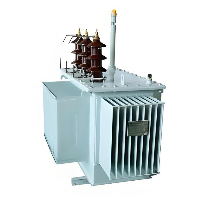
To verify the effectiveness of the aforementioned transformer grounding protection technology in construction sites, this chapter will use the power system simulation software PowerFactory to conduct transformer grounding protection simulation experiments. First, a building electrical system model is established in the simulation software, which mainly includes transformers, high and low voltage lines, loads, and other equipment. Table 1 presents the model and parameter specifications of the experimental transformer.
Item |
Parameter |
Model |
S11-M-1600/10 kVA |
Rated Capacity |
1600 kVA |
Rated Voltage |
10 kV/0.4 kV |
Rated Current |
144.2 A/2309 A |
No-load Current |
≤4% |
Short-circuit Impedance |
≤6% |
The specific structure of the transformer is shown in Figure 1.

Then, transformer grounding protection simulation experiments were conducted using three different grounding methods respectively: neutral point low-resistance grounding, neutral point high-resistance grounding, and neutral point grounding with arc-suppression coil. When setting the grounding methods, for the neutral point low-resistance grounding method, a resistor with small resistance value was selected, specifically set to 0.5 Ω, to simulate the effect of low-resistance grounding; for the neutral point high-resistance grounding method, a resistor with larger resistance value was selected, set to 10 Ω, to simulate the characteristics of high-resistance grounding.
During the experiment, the grounding current levels of the transformer under single-phase grounding faults were simulated. The specific location of the fault was set at the midpoint of one phase line on the low-voltage side of the transformer, with the fault resistance set to 100 Ω to simulate the grounding resistance during a grounding fault. In the fault simulation process, a high sampling rate data acquisition system was used to record grounding current data, with the sampling frequency set to 1000 times per second to ensure capturing subtle changes in the grounding current.
In addition to recording the grounding current value at the moment of fault occurrence, multiple time points were set, including 0.1 s, 0.5 s, 1 s, 5 s, and 10 s after the fault occurred, to observe changes in grounding current at different time points. To avoid randomness in the experimental results, grounding current data were recorded 10 times, with the average value taken as the final experimental result. Figure 2 provides a comparison of transformer grounding protection effects under different grounding methods.

As shown in Figure 2, the simulation analysis compared the grounding current characteristics of transformers under single-phase faults for neutral point low-resistance grounding, high-resistance grounding, and arc-suppression coil grounding methods. The results indicate that, during a single-phase grounding fault in transformers, the grounding current under the neutral point low-resistance grounding method is significantly higher than that under the neutral point high-resistance grounding and neutral point arc-suppression coil grounding methods.
Under the designed grounding protection technology, the average transformer grounding current was 70.11 A, which is an increase of 43.44 A and 21.62 A respectively compared to the control group technologies. This helps reduce the arc intensity at the fault point and accelerates the self-clearing capability of the fault. Therefore, the designed grounding protection technology is feasible and reliable, suitable for practical application in single-phase grounding faults of transformers, effectively protecting the operational safety of transformers in construction sites.
4.Conclusion
The grounding protection technology for transformers in construction proposes a zero-sequence overcurrent protection scheme based on the neutral point low-resistance grounding method. Through comparative experiments, the superiority of the designed grounding protection technology in main protection for transformer single-phase faults has been verified. Although some research achievements have been made, there are still certain limitations. For instance, the experimental conditions and data samples may not be comprehensive enough, requiring further validation of the universality of the conclusions.
Future research could focus on the following areas: firstly, expanding the scope of experiments and increasing data samples to improve the accuracy and universality of the conclusions; secondly, conducting in-depth studies on other protection schemes and technologies to explore more efficient and reliable transformer grounding protection methods; finally, developing higher-performance protection devices and systems in combination with practical engineering applications.