Installation and Adjustment of Vacuum Circuit Breakers
All parts and components must be inspected and approved prior to installation.
Fixtures and tools used for installation must be clean and meet assembly requirements. Fixed fasteners should be tightened using box-end, ring, or socket wrenches. Adjustable (open-end) wrenches must not be used when tightening screws near the arc extinguishing chamber.
Installation sequence must follow the specified assembly process. Fastener types and specifications must strictly comply with design requirements. In particular, the length of bolts fixing the stationary contact terminal of the arc extinguishing chamber must not be incorrect.
After assembly, the pole-to-pole distance and the positional distances of upper and lower output terminals must conform to drawing specifications.
All rotating and sliding components must move freely after assembly. Lubricating grease should be applied to friction surfaces.
After successful adjustment and testing, clean and wipe all parts thoroughly. Mark adjustable connection points with red paint to indicate position, and coat output terminals with petroleum jelly, then wrap with clean paper for protection.
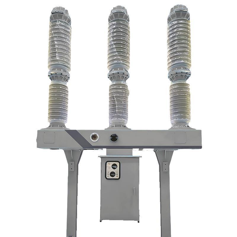
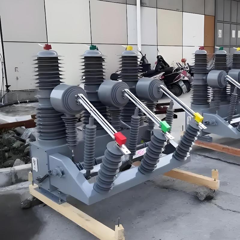
Taking the ZN39-type vacuum circuit breaker as an example, assembly is generally divided into three parts: front, upper, and rear.
Front Section Assembly Sequence:
Frame positioning → Support insulators → Horizontal insulators → Support bracket → Lower busbar → Arc extinguishing chamber and parallel insulating rods → Upper busbar → Conductive clamp with flexible connection → Contact spring seat and sleeve → Triangular crank arm.
Upper Section Assembly Sequence:
Main shaft and bearing housing → Oil damper → Insulating push rod.
Rear Section Assembly Sequence:
Operating mechanism → Opening spring → Counter, open/close indicator, grounding mark.
Integration of the Three Sections:
Connect the front and upper sections: link the adjustable joint of the insulating push rod to the triangular crank arm with a pin.
Connect the rear and upper sections: link the adjustable drive rod of the operating mechanism to the main shaft crank arm with a pin.
The assembly process is simple, intuitive, and convenient.

Preliminary adjustment primarily involves coarse tuning of the contact gap (opening distance) and contact travel (overtravel) for each pole after full assembly.
Manually close the breaker slowly to verify correct installation and connection of all components. Avoid setting excessive contact travel, as this may compress the closing spring fully (spring binding), potentially damaging components. To prevent this, initially set the adjustable joint of the insulating push rod shorter (screwed in). After confirming smooth manual operation, proceed to measure and adjust the opening distance and contact travel.
Vacuum circuit breakers can be broadly classified into two types based on the relative position of the moving contact rod axis and the closing spring axis:
Type I: Coaxial Structure – Moving contact cup axis coincides with the closing spring axis.
Type II: Offset (Non-coaxial) Structure – Moving contact rod axis is separate from the closing spring axis, with the spring mounted on the insulating push rod shaft, nearly perpendicular to the contact rod.
The calculation and adjustment methods differ slightly between these two types.
Mechanical characteristic tables for various vacuum circuit breakers specify nominal values for opening distance and contact travel. After manually performing open and close operations and measuring actual values, adjust as follows to meet technical specifications.
(1) Adjustment for Coaxial Structures
Step 1: Adjust Total Travel
Total travel = Opening distance + Contact travel.
If total travel is less than the sum of nominal values, the main shaft rotation is insufficient. Lengthen the adjustable connecting rod between the operating mechanism and main shaft crank arm. If too long, shorten the rod. This ensures total travel meets requirements.
Step 2: Adjust Distribution Between Opening Distance and Contact Travel
Adjust the threaded connection at the front end of each pole’s insulating rod.
Minimum adjustment: half a thread pitch (by turning the joint 180°).
This threaded joint also adjusts three-phase synchronization. Adjustments must balance travel values and phase synchronization. Repeat manual open/close cycles until both are within tolerance. Never exceed maximum allowable contact travel to avoid spring binding and component damage.
Lengthen connection (screw out): Opening distance ↑, Contact travel ↓
Shorten connection (screw in): Opening distance ↓, Contact travel ↑
(2) Adjustment for Offset (Non-coaxial) Structures
In this design, the closing spring axis and moving contact axis are not aligned, so total travel has no direct physical meaning. Adjustment methods differ:
Opening Distance Adjustment:
Achieved via an "opening distance adjustment shim" mounted on the frame. The shim’s height is adjusted by adding or removing layers. The top is pressed by the main shaft’s crank arm. Changing the shim height alters the main shaft’s initial angle in the open position, thereby changing the contact opening distance through the insulating push rod.
Contact Travel Adjustment:
The pre-compression height (B1) of the contact spring is fixed by the roller diameter and cannot be changed. The final compression height (B2) after closing is adjusted by:
During adjustment, simultaneously optimize three-phase synchronization, making repeated fine adjustments until all parameters are within tolerance.
Lengthen rod: B2 decreases → Contact travel increases
Shorten rod: B2 increases → Contact travel decreases
Screw in (shorten rod): B2 increases → Contact travel decreases
Screw out (lengthen rod): B2 decreases → Contact travel increases
A. Adjusting the threaded joint at the end of the insulating push rod:
B. Adjusting the length of the connecting rod between the operating mechanism and the main shaft crank arm:
(3) Auxiliary Switch Interlock Adjustment
After manually adjusting opening distance and contact travel, the auxiliary switch interlock position must be properly set before electric operation—otherwise, electrical components may be damaged.
Adjustment Procedure:
Disconnect the pin between the auxiliary switch and the main shaft crank arm linkage.
Manually close the breaker while rotating the auxiliary switch to the point just before it trips. Adjust the length of the adjustable rod and bolt so that the pin holes align approximately.
Manually open the breaker and rotate the auxiliary switch to its trip point again, ensuring pin holes align.
Repeat the process until alignment is achieved in both open and close positions, then insert the pin.
Ensure the auxiliary switch contacts open slightly before the main contacts fully close or open.
After preliminary adjustment of opening distance, contact travel, and auxiliary switch, perform electric open/close operations and measure the following mechanical characteristics:
Opening/closing time
Speed
Phase-to-phase synchronization (out-of-phase)
Closing bounce
Testing Instruments:
Optical oscillograph – highly accurate and visual
Circuit breaker analyzer – simple, fast, and sufficiently accurate for field use
(Specific test methods are not detailed here.)
After testing, perform fine adjustments on any out-of-spec parameters to achieve optimal performance.
(1) Fine Adjustment of Synchronization
Identify the phase with the greatest timing deviation. If one pole closes too early (or late), slightly increase (or decrease) its opening distance by turning the insulating rod’s adjustable joint in (for earlier closure) or out (for later closure) by about half a turn. Typically, this can reduce synchronization error to within 1 ms.
(2) Fine Adjustment of Opening/Closing Speed
Speed is influenced by multiple factors, but key adjustable elements are the opening spring tension and contact travel.
Closing speed too high, opening speed too low:
Increase contact travel or tighten the opening spring.
Closing speed acceptable, opening speed too low:
Increase total travel by 0.1–0.2 mm, which increases contact travel and improves opening speed.
Opening speed too high:
Reduce contact travel by 0.1–0.2 mm to lower speed.
After adjustment, re-measure opening distance and contact travel to ensure they remain within specified ranges.
(3) Elimination of Closing Bounce
Closing bounce may result from:
Excessive closing impact rigidity, causing axial rebound of the moving contact.
Poor guidance of the moving contact rod, resulting in excessive wobble.
Excessive clearance in transmission links, especially between the contact spring and the conductive rod.
Poor perpendicularity between the contact surface and the central axis, causing lateral slip upon contact (appears as "bounce" on oscillograms).
Mitigation Measures:
Design should avoid excessive mechanical rigidity (not adjustable post-manufacture).
Ensure proper guidance clearance for the moving contact rod.
In coaxial designs, the contact spring connects directly to the conductive rod—no intermediate links, hence less bounce.
In offset designs, a triangular crank arm with three pins introduces three potential clearances, increasing bounce risk.
If bounce is caused by poor perpendicularity of the arc extinguishing chamber contact surface, try rotating the chamber by 90°, 180°, or 270° during assembly to find the optimal alignment. If ineffective, replace the arc extinguishing chamber.
Ensure all screws are fully tightened during adjustment to avoid vibration interference.
After all mechanical characteristics meet specifications, perform 50 operation cycles (open/close and reclose) at maximum, minimum, and rated control voltage as per factory requirements.
After 50 operations, re-measure all mechanical parameters. Results should closely match initial measurements to pass.
Finally, perform:
Circuit resistance test
Power frequency withstand voltage tests on primary and secondary circuits
Only units passing all tests are approved for shipment.