Advantages and Disadvantages of Double-Busbar Configuration in Substations
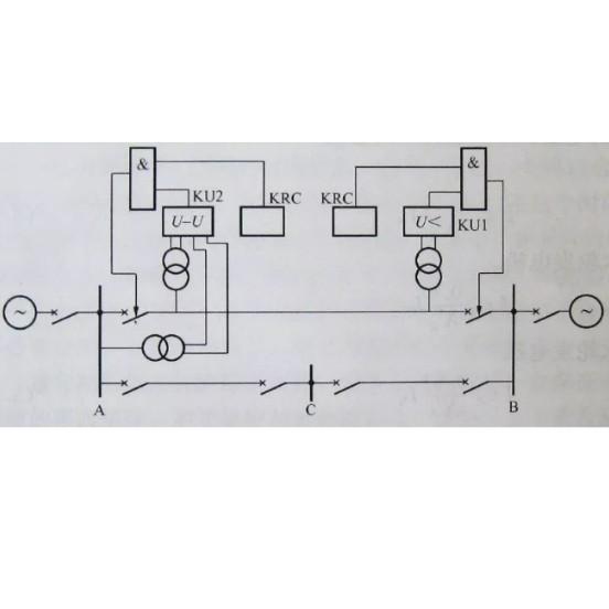
A substation with double-busbar configuration employs two sets of busbars. Each power source and each outgoing line is connected to both busbars via one circuit breaker and two disconnectors, allowing either busbar to serve as the working or standby busbar. The two busbars are interconnected through a bus tie circuit breaker (referred to as the bus coupler, QFL), as shown in the figure below.

I. Advantages of Double Busbar Connection
Flexible operation modes. It can operate with both busbars energized simultaneously by evenly distributing power sources and outgoing lines between the two busbars and closing the bus tie circuit breaker; alternatively, it can operate as a single busbar with sectionalization by opening the bus tie circuit breaker.
When one busbar is under maintenance, power sources and outgoing lines can continue operating without interrupting power supply to customers. For example, when Bus I needs maintenance, all circuits can be transferred to Bus II—commonly known as “bus transfer.” The specific steps are as follows:
First, check whether Bus II is in good condition. To do this, close the disconnectors on both sides of the bus tie circuit breaker QFL, then close QFL to charge Bus II. If Bus II is intact, proceed to the next steps.
Transfer all circuits to Bus II. First, remove the DC control fuse of QFL, then sequentially close the Bus II-side bus disconnectors of all circuits and open the Bus I-side disconnectors.
Reinstall the DC control fuse of QFL, then open QFL and its disconnectors on both sides. Bus I can now be taken out of service for maintenance.
When maintaining the bus disconnector of any circuit, only that circuit needs to be de-energized. For example, to maintain bus disconnector QS1, first open the circuit breaker QF1 of outgoing line WL1 and its disconnectors on both sides, then transfer the power source and all other outgoing lines to Bus I. QS1 is then completely isolated from the power source and can be safely maintained.
In the event of a fault on Bus I, all circuits can be rapidly restored. When a short-circuit fault occurs on Bus I, circuit breakers of all power source circuits automatically trip. At this point, open the circuit breakers of all outgoing lines and their Bus I-side disconnectors, close the Bus II-side bus disconnectors of all circuits, and then reclose the circuit breakers of all power sources and outgoing lines—thus quickly restoring all circuits on Bus II.
When maintaining any line circuit breaker, the bus tie circuit breaker can temporarily substitute for it. Taking the maintenance of QF1 as an example, the operational steps are: first transfer all other circuits to the other busbar so that QFL and QF1 are connected in series via the busbar. Then open QF1 and its disconnectors on both sides, disconnect the wiring at both ends of QF1, and bridge the gap with a temporary current-carrying “jumper.” Next, close the disconnectors on both sides of the jumper and the bus tie circuit breaker QFL. Thus, outgoing line WL1 is now controlled by QFL. During this process, WL1 experiences only a brief power interruption. Similarly, if an abnormality (e.g., fault, failure to operate, or prohibited operation) is detected in an in-service line circuit breaker, all other circuits can be transferred to the other busbar to form a series power supply circuit with QFL and the faulty breaker via the busbar. Then QFL is opened, followed by opening the disconnectors on both sides of the faulty breaker, thereby taking it out of service.
Easy expansion. The double busbar configuration allows extension on either side without affecting the power source and load distribution on the busbars. Expansion work does not cause outages in existing circuits.
II. Disadvantages of Double Busbar Connection
During bus transfer operations, all load current circuits must be switched using disconnectors, making the procedure complex and prone to operator error.
A fault on Bus I causes a brief total outage of all incoming and outgoing lines (during the bus transfer period).
When any line circuit breaker is under maintenance, that circuit still requires either a complete outage or a short interruption (before the bus tie circuit breaker substitutes for it).
A large number of bus disconnectors are required, and the increased busbar length makes the switchgear arrangement more complex, resulting in higher investment costs and larger footprint.
Application scope:
For 6 kV switchgear, when short-circuit current is high and reactors are needed on outgoing lines;
For 35 kV switchgear with more than 8 outgoing circuits;
For 110 kV to 220 kV switchgear with more than 5 outgoing circuits.