1. תקלות בתקיעת והצגתה של ציוד חשמלי בתחנת טרנספורמציה
1.1 תקלות בטרנספורמר
במהלך התקנה והצגתה של ציוד חשמלי בתחנת טרנספורמציה, כמכשיר מרכזי, התקנה והצגתה של הטרנספורמר הם חשובים ביותר. להלן בעיות ספציפיות שעשויות להתעורר במהלך התקנה והצגתה של הטרנספורמר.
1.1.1 בעיות התקנה
מיקום ותקיעה: מיקום התקנת הטרנספורמר צריך לעמוד בדרישות התכנון כדי להבטיח שהוא יציב ומאונך. מיקום התקנה לא נכון או תקיעה לא בטוחה עלולים לגרום לטרנספורמר לרעוד או להזוז במהלך ההפעלה, מה שיכול להשפיע על פעילותו הנורמלית.
בעיות חיבור: החיבור של הטרנספורמר חייב להתבצע באופן מדוקדק בהתאם לשרטוטים והכללים. חיבור לא נכון עלול להוביל לסיכונים כמו קצר מעגל ודליפות חשמל. בנוסף, יש לוודא שהחיבור הוא מתוח בכדי יחס. חיבור רופף מדי עלול לגרום לקשר גרוע, בעוד חיבור חזק מדי עלול לפגוע בחיבורים.
טיפול בבודד: במהלך התקנת הטרנספורמר, הטיפול בבודד הוא קריטי. בחירת חומרי בידוד לא נכונים או בנייה לא תקנית עלולים להוביל להפחתה בביצועי הבידוד, ובכך לעורר תקלות חשמליות.
1.1.2 בעיות הצגתה
מבחן סבילות לחשמל: לאחר התקנת הטרנספורמר, נדרש מבחן סבילות לחשמל כדי לבדוק את ביצועי הבידוד שלו. אם תוצאות המבחן אינן עומדות בדרישות, זה עשוי להצביע על פגמים בבידוד הפנימי של הטרנספורמר או נזק שנגרם במהלך ההתקנה.
בדיקות ללא מטען ומטע"א: ניתן להשתמש בבדיקות ללא מטען ומטע"א כדי לנתח אם פרמטרי הביצועים של הטרנספורמר עומדים בדרישות התכנון. נתונים חריגים במבחנים עשויים להצביע על תקלות פנימיות בטרנספורמר או בעיות שהתעוררו במהלך ההתקנה.
כינוס טמפרטורה ורעש: במהלך תהליך ההצגתה, יש לעקוב בקפידה אחר הטמפרטורה והרעש של הטרנספורמר. טמפרטורה או רעש מוגברים עלולים להצביע על בעיות כגון פיזור חום גרוע וברזל ליבה רופף בטרנספורמר.
1.2 תקלות במתג גלאי
1.2.1 תקלות במהלך התקנה
בדיקה חסרה של הקו: לפני התקנת המתג הגלאי, יש לבדוק את כל קו המתג הגלאי. בדיקה בלתי מספקת עלולה להתעלם מכך שאותות, ידיות פעולה וכדומה בקו עומדים בדרישות, מה שיכול להוביל לסיכונים פוטנציאליים במתג הגלאי לאחר ההתקנה.
נזק למגן בידוד: במהלך תהליך ההתקנה, יש להבטיח שהמגן הבידודי של המתג הגלאי הוא בשלמותו. כל נזק קלים עלול להוביל להפחתה בביצועי הבידוד של המתג הגלאי, ובכך ליצור סיכונים.
בעיות התקנה בшуроверים: בעת התקנת המתג הגלאי, יש לה затронутый текст был переведен на иврит, но кажется, что часть перевода была случайно прервана. Давайте продолжим перевод с места, где он остановился, чтобы обеспечить полноту и точность:
בעיות התקנה בшуроверים: בעת התקנת המתג הגלאי, יש להשתדל להתקין את ארבעת השוроверים הפינות באופן מוצק. אם השוроверים אינם מותקנים נכון או שהם מותקנים בצורה הדוקה מדי, זה עשוי להשפיע על היציבות והביצועים של המתג הגלאי.
1.2.2 תקלות במהלך ההצגתה
תקלות במוט בידוד: במהלך תהליך ההצגתה, יש לבדוק את המרכיב הבידודי ואת העמידה של מוט הבידוד של המתג הגלאי [1]. אם קיימות בעיות במוט הבידוד, כגון הפחתה בביצועי הבידוד או ערכים חריגים של העמידה, זה ישפיע ישירות על פעילתו הנורמלית של המתג הגלאי.
תקלות במקלעי הסגירה והפתיחה: במהלך ההצגתה, יש למדוד את העמידה הבידודית ואת העמידה הקצרה של מקלעי הסגירה והפתיחה. אם הפרמטרים הללו אינם עומדים בדרישות, זה עשוי למנוע מהמתג הגלאי לסגור או לפתוח באופן תקין.
זמנים חריגים לסגירה ופתיחה: זמני הסגירה והפתיחה של המתג הגלאי הם מדדים חשובים במהלך תהליך ההצגתה. אם זמני הסגירה והפתיחה אינם עומדים בדרישות התכנון, זה עשוי להשפיע על ביצועי ההגנה של המתג הגלאי.
זמן נảy משני גבוה מדי: במהלך תהליך ההצגתה, יש למדוד את זמן הניסוי של הקשרים כאשר המתג הגלאי נסגר. זמן ניסוי גבוה מדי עלול להוביל לתשישות מוגברת של הקשרים, ובכך להשפיע על משך החיים של המתג הגלאי.
1.3 תקלות במתג ניתוק
1.3.1 תקלות במהלך התקנה
שבר בסוללת הקרמיקה: זה בדרך כלל קשור איכות המוצר, האיכות הכללית של המתג ניתוק, ושיטת הפעולה. למשל, במהלך תהליך השריפה של סוללת הקרמיקה, עלולים להיווצר בעיות כגון שריפה חסרה, צפיפות לא אחידה, וקשיחות רעילה עקב בקרה לא נכונה. בנוסף, בדיקה לא תקינה עלולה גם להוביל לאסSEMBLY OF INDIVIDUAL LOW-QUALITY PORCELAIN INSULATORS INTO THE PRODUCT, THUS CREATING SAFETY HAZARDS DURING THE INSTALLATION PROCESS.
Overheating of the Conductive Circuit: This is mainly caused by the fatigue and deterioration of the compression spring of the static contact finger, unilateral contact of the static contact finger, and the increase in contact resistance during long - term operation. In addition, poor silver - plating process of the contact, easy wear and copper exposure, dirty contact surface, insufficient insertion of the contact, rusty bolts, etc. may also lead to heating problems.
Mechanism Problems: This is mainly reflected in operation failures, such as refusal to operate or the switch not being in place. Usually, it is caused by poor sealing or rust and water ingress of the mechanism box, resulting in serious rust of the mechanism, dry lubrication, and increased operation resistance [2].
Difficult Transmission: This is mainly due to the rust of the transmission system of the disconnector, resulting in large transmission resistance, making it difficult to open or close the switch.
1.3.2 Faults during Debugging
Failure of Electric Operation: This may be caused by problems in the operation power supply circuit, power supply circuit, or reasons such as fuse fusing, loosening, and abnormal electrical interlocking circuits.
Incomplete Closing or Non - Synchronous Three - Phase: Such problems are mostly caused by mechanism rust, jamming, and improper maintenance and debugging.
Heating of the Contact Part: During the debugging process, heating of the contact part may be found. This is usually caused by reasons such as the loosening of the compression spring or screws, oxidation of the contact surface leading to an increase in contact resistance, too small contact area between the blade and the static contact, excessive load operation, and arc - burning of the contact during the closing and opening process or improper force resulting in an incorrect contact position.
1.4 Transformer Faults
1.4.1 Faults during Installation
Internal Winding Short - Circuit: This is usually caused by the rupture or breakdown of the insulation material between the windings. An internal winding short - circuit will cause the transformer to fail and may even trigger more serious electrical failures.
Terminal Loosening or Poor Contact: When connecting the transformer, terminal loosening or poor contact will lead to unstable output signals and measurement errors.
Housing Electric Leakage: This usually occurs in high - humidity and corrosive environments. Electric leakage will not only lead to measurement errors but also pose a safety hazard.
1.4.2 Faults during Debugging
Ratio Deviation: The ratio of the transformer may deviate from the normal value, which will affect the accuracy of measurement. During the debugging process, a current source with known accuracy needs to be used for testing to ensure the accuracy of the ratio.
Core Saturation: Under high - current conditions, the core of the transformer may saturate, resulting in distortion and error of the output voltage. During debugging, it is necessary to check whether the output is linearly related to the input current to avoid the problem of core saturation [3].
Temperature Drift: Temperature changes may cause the performance of the current transformer to drift. Testing the output of the current transformer under different temperature conditions can check for the presence of temperature drift.
External Magnetic Field Interference: The external magnetic field may interfere with the operation of the current transformer. Testing the output of the current transformer under the condition of no external current can observe whether it is affected by the external magnetic field.
1.5 Lightning Arrester Faults
1.5.1 Faults during Installation
Improper Installation Position: The installation position of the lightning arrester needs to be carried out strictly in accordance with the regulations. An installation position that is too low or too high may affect its lightning protection effect. In addition, installing the lightning arrester in a place vulnerable to mechanical damage, serious pollution, or chemical corrosion may also lead to a decline in its performance or damage.
Connection Problems: Poor contact or loosening of the connection wires of the lightning arrester will prevent it from working properly. For example, a too - small cross - sectional area of the connection wires, insecure connection, or corrosion may all lead to failures.
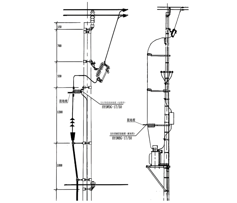
Grounding Problems: The grounding of the lightning arrester is an important part of its normal operation. An excessive grounding resistance or a broken grounding wire will seriously affect the effect of the lightning arrester. The connection diagram of the lightning arrester is shown in Figure 1.
Excessive Leakage Current: If the leakage current of the lightning arrester exceeds the specified value during debugging, it may be caused by reasons such as internal moisture, insulation aging, or damage of the lightning arrester. In such cases, timely maintenance or replacement is required.
Excessive Residual Voltage: After the lightning arrester operates, it should be able to quickly reduce the voltage to a safe level. If excessive residual voltage is detected during debugging, it may be due to the damage or aging of internal components of the lightning arrester. This also calls for maintenance or replacement.
Insensitive Operation: During the debugging process, if the lightning arrester is found to be insensitive or fails to operate, it may be caused by internal mechanical failures, poor electrical connections, or aging [4]. In this situation, a detailed inspection and repair of the lightning arrester are necessary.
2. Fault Handling in the Installation and Debugging of Substation Electrical Equipment
2.1 Principles of Fault Handling in the Installation and Debugging of Substation Electrical Equipment
Safety - First Principle: When dealing with faults, the safety of personnel is the top priority. It is essential to strictly abide by safety operation procedures to avoid casualties or further accidents.
Rapid Response Principle: Once a fault occurs, the staff should respond promptly and handle it in a timely manner. Do not underestimate the fault due to its small - scale or inconspicuous symptoms to ensure the problem is resolved in a timely manner.
Inspection - Before - Treatment Principle: Before handling a fault, a comprehensive inspection should be carried out first to identify the specific location and cause of the fault, so as to deal with it in a targeted manner and avoid misjudgment or delay in repair time.
Combination of Repair and Prevention Principle: While handling the fault, experience should be summarized, the root cause of the fault should be identified, and corresponding preventive measures should be taken to avoid the recurrence of similar faults.
2.2 Procedures for Fault Handling in the Installation and Debugging of Substation Electrical Equipment
Rapid Response Principle: Once a fault occurs, the staff should respond promptly and handle it in a timely manner. Do not underestimate the fault due to its small - scale or inconspicuous symptoms to ensure the problem is resolved in a timely manner.
Inspection - Before - Treatment Principle: Before handling a fault, a comprehensive inspection should be carried out first to identify the specific location and cause of the fault, so as to deal with it in a targeted manner and avoid misjudgment or delay in repair time.
Combination of Repair and Prevention Principle: While handling the fault, experience should be summarized, the root cause of the fault should be identified, and corresponding preventive measures should be taken to avoid the recurrence of similar faults.
3. Case Analysis of Faults in the Installation and Debugging of Substation Electrical Equipment
3.1 Common Faults in the Installation and Debugging of Substation Electrical Equipment
3.2 Typical Faults in the Installation and Debugging of Substation Electrical Equipment
Transformer Faults
Overheating: It may be caused by a cooling system failure or overload. It is necessary to check the cooling system and load conditions of the transformer.
Abnormal Noise: Usually, it is caused by impurities inside the transformer or structural looseness. Cleaning and tightening treatments should be carried out.
Oil Leakage: It may be caused by the aging or damage of the sealing parts of the insulating oil. It is necessary to check and replace the sealing parts.
Switchgear Faults
Poor Contact: It may be caused by loose wiring or contamination of metal contacts. Cleaning and tightening treatments should be carried out.
Tripping: It may be caused by improper settings of overload protection devices or equipment failures. It is necessary to check the protection parameters and equipment status.
Transmission Line Faults
Insulation Damage: It may be caused by equipment defects, insulation aging, or environmental humidity. Insulation detection and replacement of damaged components should be carried out.
Electric Leakage: It may be caused by line damage or poor contact. Partial discharge testing and insulation treatment should be carried out.
Protection Device Faults: Protection devices may experience misoperation or refusal to operate. It is necessary to check the wiring, power supply, and setting parameters of the protection devices.
Grounding Faults: Problems such as excessive grounding resistance or damaged grounding wires may lead to grounding faults. It is necessary to check the grounding system and grounding resistance.
Other Faults: Problems with distribution boxes (such as grounding wire problems, non - standard box openings, etc.), improper equipment grounding, and equipment conductor connection problems need to be inspected and repaired according to specific conditions.
3.3 Special Faults in the Installation and Debugging of Substation Electrical Equipment
Overload Faults: Overload faults are usually caused by excessive load or equipment damage. Such faults are relatively common in substation electrical equipment and are likely to cause equipment overheating and burnout, seriously affecting the normal operation of the power grid system. When dealing with such faults, the first step is to adjust the system load distribution to avoid equipment overload, and then check for any equipment damage and carry out timely repair or replacement.
Short - Circuit Faults: Short - circuit faults are relatively serious faults in substation electrical equipment. They may be caused by poor internal circuit connections of equipment or damage to the grounding wires of external equipment. Short - circuit faults are likely to cause equipment damage, fires, and other dangerous situations, severely affecting the normal operation of the power grid system. When dealing with such faults, the power supply should be quickly cut off, the cause of the short - circuit should be checked, and repairs should be carried out.
Grounding Faults: Grounding faults may be caused by excessive grounding resistance, damaged grounding wires, etc. Such faults will affect the normal operation of the equipment and may trigger dangerous situations such as fires. When dealing with such faults, it is necessary to check whether the grounding device is intact and eliminate problems such as poor contact of the grounding resistance to ensure that the grounding resistance meets the requirements.
Insulation Faults: Insulation faults are usually caused by equipment defects, insulation aging, environmental humidity, etc. When insulation faults occur, the equipment often cannot operate normally, and in severe cases, it may cause damage to the staff and equipment. When dealing with such faults, insulation detection and maintenance should be carried out to improve the insulation level of the equipment and prevent the occurrence of insulation faults.
4. Abnormal Phenomena in the Installation and Debugging of Substation Electrical Equipment
Distribution Box Installation Faults: Gaps between the distribution box and the ground may be due to the inability of the grounding wire to meet the specification requirements under repeated operation conditions; non - standard openings of the distribution box body, with too many welding openings, resulting in damage to the protective paint of the box body; limited space in the distribution box, affecting manual operation.
Conductor Quality Problems: The color and quantity of conductors do not meet the requirements, which may easily cause confusion for installers. For example, the neutral wire, live wire, and ground wire have the same color, creating a safety hazard.
Conduit Laying Problems: The conduits are too short or the wires are exposed, and there is an overlapping phenomenon between the distribution box and the concealed pipeline. Construction workers do not properly control the depth of the conduits buried in the wall or ground,


