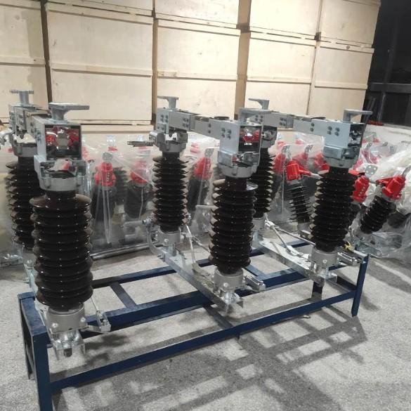
Common Issues and Handling Measures for 145kV Disconnector Control Circuits

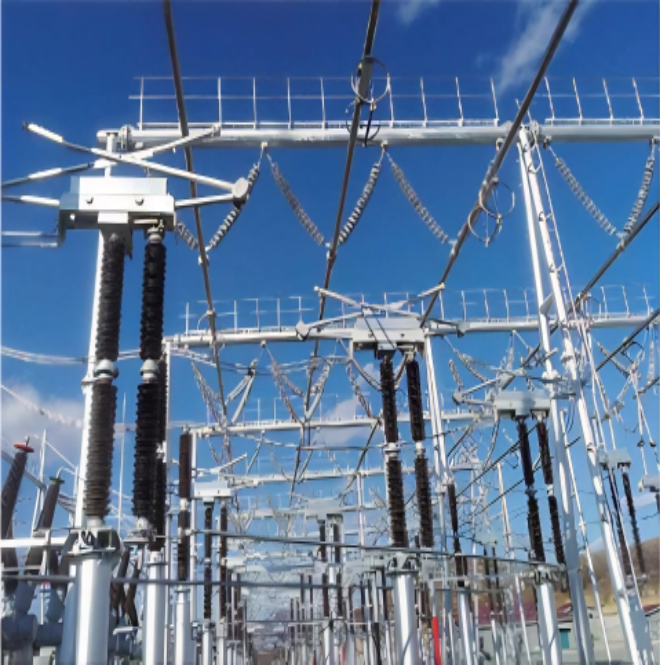
The 145 kV disconnector is a critical switching device in substation electrical systems. It is used in conjunction with high-voltage circuit breakers and plays an important role in power grid operation:
First, it isolates the power source, separating equipment under maintenance from the power system to ensure personnel and equipment safety;Second, it enables switching operations to change the system operating mode;Third, it is used to interrupt small-current circuits and bypass (loop) currents.
Regardless of the state of the power system, the disconnector must operate reliably. The reliability of its operation depends not only on good mechanical performance but also on whether its control circuit meets production requirements. If safety hazards exist in the disconnector’s control circuit, serious accidents may occur.
1. Analysis of the Control Circuit Principle of 145 kV Disconnectors
The control circuit of a 145 kV disconnector mainly consists of two parts: the motor control circuit and the motor power supply circuit.The control circuit includes three operation modes: local manual opening/closing, local electric opening/closing, and remote control opening/closing. Switching between “remote” and “local” modes is performed via the disconnector operating handle in the bay terminal box. The control circuit primarily comprises the interlocking circuit, the terminal box operating handle, five-prevention (5P) devices, measurement & control contacts, open/close push buttons, contactors, and other components.
The interlocking circuit mainly implements:
Circuit breaker interlock to prevent disconnector operation when the circuit breaker is closed;
Mutual interlock between the disconnector and the earthing switch.
These interlocks are achieved by series-connecting normally open (NO) and normally closed (NC) contacts of the circuit breaker, disconnector, and earthing switch into the control circuit.Additionally, there are GBM (bus tie) and PBM (bypass) interlocks.
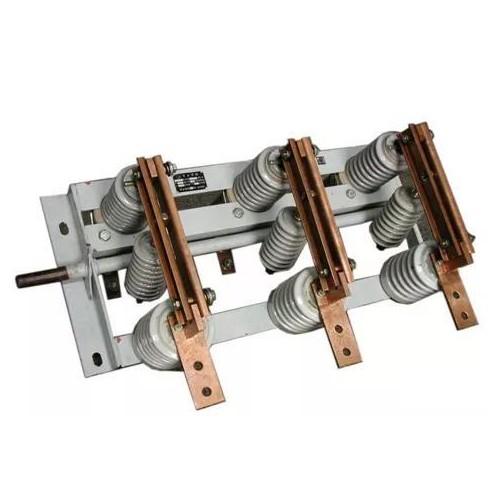
The motor power supply circuit is the main circuit, consisting of the motor, contacts from contactors in the control circuit, power miniature circuit breakers (MCBs), limit switches, etc. In actual operation, the motor is controlled by the control circuit to rotate forward or reverse, thereby actuating the disconnector’s opening or closing. A pair of contacts from the closing and opening contactors are connected in series in the power circuit. For closing, the phase sequence is ABC; for opening, the sequence is reversed to ACB, thus reversing the motor direction to operate the blades.
The remote monitoring system uses line measurement & control devices to remotely control the disconnector’s opening and closing. After the disconnector reaches its end position (fully open or closed), the power circuit must be disconnected; otherwise, the motor will continue running until it burns out. To prevent this, limit switches are installed in series in the power circuit. When the disconnector reaches its end position, the limit switch opens and stops the motor.
To prevent dangerous operations—such as opening/closing the disconnector under load or closing the earthing switch while energized—an electrical interlock is incorporated into the control circuit. Electric operation is only enabled when all five-prevention conditions are satisfied.

2. Types of Control Circuit Faults
Classified by the number of faulty phases, faults can be divided into three-phase faults and phase-loss faults (including one-phase or two-phase failures).
Based on operational scenarios, faults can be further categorized into four types:
Local open/close fails, but remote operation works.
Remote open/close fails, but local operation works.
Both remote and local electric operations fail, but manual operation via contactor magnetic pull-in is possible.
Only manual crank operation is possible.
3. Fault Phenomena of Disconnectors
During on-site commissioning, it was observed that disconnectors that previously operated normally via remote/local electric control suddenly failed to open or close. In some cases, after the motor operating mechanism remained energized for an extended period, the disconnector became inoperable—and this issue recurred repeatedly. Such faults severely disrupted commissioning progress and posed safety risks to substation operation, necessitating immediate troubleshooting to identify the root cause.
4. Fault Handling and Root Cause Analysis
4.1 Faulty Open/Close Contactors
If both local and remote operations fail, go to the terminal box and attempt a local open/close operation once. If the contactor coil does not energize properly, the contactor is likely faulty.
Under normal conditions, pressing and releasing the open/close button briefly is sufficient to complete the operation. This is because, upon pressing the button, the contactor not only activates its main power contacts but also closes a self-holding contact. Even after releasing the button, the contactor remains energized to keep the motor running.
If the motor turns slightly and then stops immediately, but operates normally when the button is held down continuously, the self-holding contact of the contactor is likely damaged. To confirm:
Turn off the motor power MCB;
Press the open/close button;
Use a multimeter to check for voltage across the self-holding contact.
If no voltage is present, the contact is damaged.
4.2 Incorrect Motor Rotation Direction (Phase Sequence Error)
The main circuit includes motor power connections and contactor contact positions. Incorrect motor rotation is usually caused by miswired contacts or reversed phase sequence in the three-phase power supply to the motor.
Troubleshooting steps:
Verify that both control and motor power MCBs are closed, and use a multimeter to confirm normal voltage at the lower terminals of the main circuit.
Disconnect motor power, keep control power on, and press the local open/close buttons in the mechanism box. Measure whether the corresponding contactor contacts conduct as expected.
If the problem persists, disconnect both control and motor power, and check if the yellow, green, and red phase wires are incorrectly swapped at the motor terminals.
In one case, two newly installed bays had inconsistent yellow-green-red wiring, which altered the motor phase sequence. After correcting the wiring, operation returned to normal.
Other common hidden issues in disconnector control circuits include: aged contactors, limit switches not reaching proper positions, missing interlocks (e.g., busbar disconnector not interlocked with busbar earthing switch, or line earthing switch not voltage-verified before closing).
Any component in the circuit can fail. When a fault occurs, carefully inspect the continuity of the entire control loop, eliminate sections step by step, narrow down the fault location, replace the faulty component, and restore the circuit. Therefore, operators must thoroughly understand the operating principles so they can quickly identify faults, clarify troubleshooting logic, and apply systematic methods to resolve issues effectively.
4.3 Other Faults
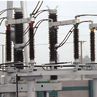
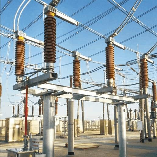
The 145 kV disconnector is frequently operated and critically impacts the safe operation of power plants and substations; thus, ensuring its operational reliability is essential. In practice, after the circuit breaker opens, the disconnector is opened to create a visible isolation point between maintenance equipment and live parts, providing sufficient safety clearance for personnel.
Besides the above two fault types, other common issues include:
(1) Local open/close failure while remote operation still works.To troubleshoot: first check the “remote/local” selector switch. Use a multimeter to verify whether voltage reaches the measurement & control device when the switch is set to “remote.” If not, replace the switch; if voltage is present, inspect wiring for loose terminals or incorrect connections.
(2) Failure of local operation due to damaged open/close push buttons.
Two diagnostic methods:
Live test: press the button and use a multimeter to check if voltage passes through;
De-energized test: turn off control power, press the button, and use the multimeter’s continuity function to check if the button contacts close.
If confirmed faulty, replace the button to restore function.
5.Conclusion
Generally, 145 kV disconnector faults occur during equipment operation, especially in summer when electricity demand surges and opportunities for scheduled outages are minimal. Given their high usage and critical safety requirements, the condition of disconnectors directly affects the safe operation of power plants and substations. Therefore, maintenance personnel must fully understand and master disconnector fault diagnosis methods to enhance their analytical capabilities and technical proficiency. This enables effective prevention of unintended operations, improves fault detection and resolution rates, and ultimately ensures the safety and stability of the power grid.