10 kV VCB Faults: The 4 Most Common Issues You Must Know

Common Vacuum Circuit Breaker Faults and On-Site Troubleshooting by Electrical Engineers
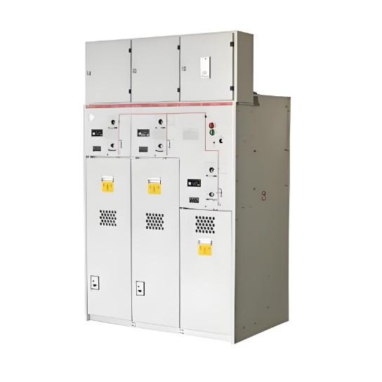
As vacuum circuit breakers are widely used in the power industry, performance varies significantly among manufacturers. Some models offer excellent performance, require minimal maintenance, and ensure high power supply reliability. Others suffer from frequent issues, while a few have severe defects that may cause over-level tripping and large-scale blackouts. Let’s explore real-world fault handling by electrical engineers to gain practical experience and master comprehensive maintenance techniques.
1. Reduced Vacuum in Vacuum Interrupter
1.1 Fault Phenomenon
Vacuum circuit breakers interrupt current and extinguish arcs within the vacuum interrupter. However, most lack built-in qualitative or quantitative vacuum monitoring, making vacuum loss a hidden (latent) fault—far more dangerous than obvious failures.
1.2 Root Causes
Defects in the vacuum bottle’s material or manufacturing process, causing micro leaks.
Issues with the bellows material or fabrication, leading to leaks after repeated operations.
In separate-type VCBs (e.g., those with electromagnetic operating mechanisms), large linkage travel affects synchronization, bounce, and over-travel, accelerating vacuum degradation.
1.3 Hazards
Reduced vacuum severely impairs the breaker’s ability to interrupt fault currents, drastically shortens service life, and may lead to explosions.
1.4 Solutions
During scheduled outages, use a vacuum tester to perform qualitative vacuum checks and confirm adequate vacuum levels.
Replace the vacuum interrupter if vacuum loss is detected, and conduct travel, synchronization, and bounce tests afterward.
1.5 Preventive Measures
Choose vacuum breakers from reputable manufacturers with proven, mature designs.
Prefer integrated designs where the interrupter and operating mechanism are combined.
During patrols, check for external arcing on the vacuum bottle. If present, vacuum integrity is likely compromised—schedule immediate replacement.
During maintenance, always test synchronization, bounce, travel, and over-travel to ensure optimal performance.
2. Failure to Trip (Trip Rejection)
2.1 Fault Symptoms
Remote control fails to trip the breaker.
Manual local tripping fails.
Relay protection operates during faults, but the breaker fails to trip.
2.2 Root Causes
Open circuit in the trip control loop.
Open trip coil.
Low operating voltage.
Increased trip coil resistance, reducing tripping force.
Deformed trip rod causing mechanical binding and reduced force.
Severely deformed trip rod causing complete jamming.
2.3 Hazards
Trip failure during faults leads to over-level tripping, expanding the fault scope and causing widespread outages.
2.4 Solutions
Check for open circuits in the trip control loop.
Inspect the trip coil for continuity.
Measure trip coil resistance for abnormalities.
Examine the trip rod for deformation.
Verify normal operating voltage.
Replace copper trip rods with steel ones to prevent deformation.
2.5 Preventive Measures
Operators: If trip/close indicator lights are off, immediately check for open control circuits.
Maintenance staff: During outages, measure trip coil resistance and inspect trip rod condition. Replace copper rods with steel.
Perform low-voltage trip/close tests to ensure reliable operation.
3. Spring Mechanism – Charging Circuit Faults
3.1 Fault Symptoms
After closing, the breaker cannot trip (insufficient energy).
The storage motor runs continuously, risking overheating and burnout.
3.2 Root Causes
Limit switch installed too low: Cuts motor power before spring is fully charged → insufficient energy for tripping.
Limit switch installed too high: Motor stays energized after full charge.
Faulty limit switch → motor fails to stop.
3.3 Hazards
Incomplete charging may cause trip failure during faults, leading to over-level tripping.
Motor burnout renders the breaker inoperable.
3.4 Solutions
Adjust limit switch position for accurate motor cutoff.
Replace damaged limit switches immediately.
3.5 Preventive Measures
Operators: Monitor the "spring charged" indicator during operation.
Maintenance: After servicing, perform two local trip/close operations to verify proper function.
4. Poor Synchronization & Excessive Contact Bounce
4.1 Fault Phenomenon
This is a hidden fault—only detectable via mechanical characteristic tests (e.g., timing analyzers).
4.2 Root Causes
Poor mechanical quality of the breaker body; repeated operations cause misalignment and high bounce.
In separate-type breakers, long linkage rods cause uneven force transmission, increasing phase-to-phase timing differences and bounce.
4.3 Hazards
High bounce or poor synchronization severely impacts fault current interruption, shortens lifespan, and may cause explosions. Due to its hidden nature, this fault is especially dangerous.
4.4 Solutions
Adjust the length of the three-phase insulating pull rods to bring synchronization and bounce within acceptable limits (while maintaining proper travel and over-travel).
If adjustment fails, replace the faulty phase’s vacuum interrupter and re-adjust.
4.5 Preventive Measures
Replace aging separate-type breakers with integrated (monobloc) designs to reduce failure risks.
During maintenance, always perform mechanical characteristic tests to detect and resolve issues early.
Final Note: Environmental Protection
Never overlook environmental impacts. Ensure clean, dry, vibration-free, and temperature-controlled conditions to guarantee safe and reliable operation of vacuum circuit breakers.