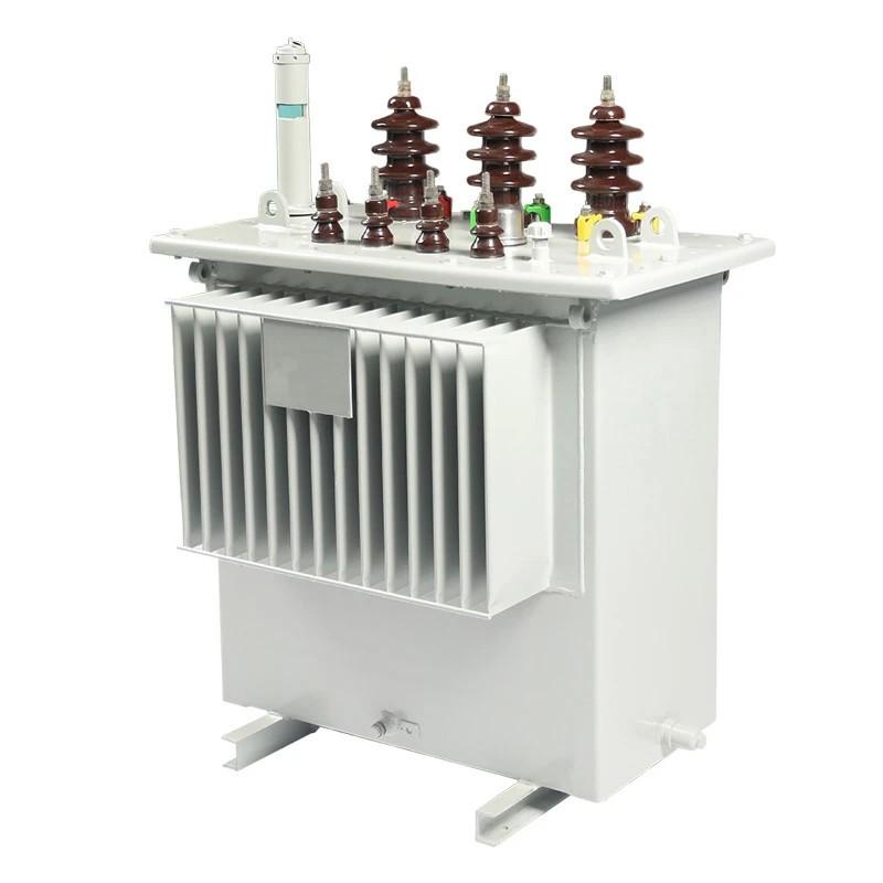
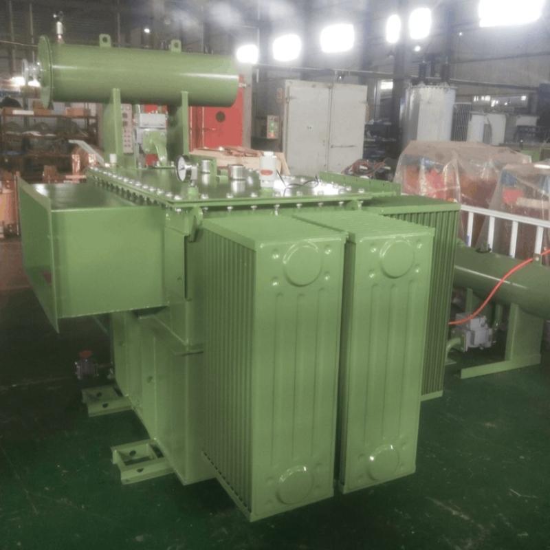
1.Transformer Maintenance and Inspection
Open the low-voltage (LV) circuit breaker of the transformer under maintenance, remove the control power fuse, and hang a “Do Not Close” warning sign on the switch handle.
Open the high-voltage (HV) circuit breaker of the transformer under maintenance, close the grounding switch, fully discharge the transformer, lock the HV switchgear, and hang a “Do Not Close” warning sign on the switch handle.
For dry-type transformer maintenance: first clean the porcelain bushings and enclosure; then inspect the enclosure, gaskets, and porcelain bushings for cracks, discharge marks, or aged rubber gaskets; check cables and busbars for deformation; replace any cracked components.
Check that busbar contact surfaces remain clean; remove oxidation layers and apply power compound grease.
Inspect the transformer grounding for integrity; check if the grounding conductor is corroded; replace severely corroded grounding conductors.
Tighten terminal screws, pins, grounding screws, and busbar connection screws. If looseness is found, remove the screws, lightly file the contact surface with a fine flat file, or replace spring washers and screws until good contact is achieved.
Clean dust from around the transformer and its accessories; inspect fire protection equipment and ventilation systems for proper operation.
2. Busway Maintenance and Inspection
The maintenance and inspection of busways shall follow the procedures below:
Check whether the connecting bolts at busway joints and the mounting bracket bolts are loose.
Verify that the total load current does not exceed the rated or design current of the main busway, and check the ambient temperature at the installation site.
Before busway maintenance, de-energize the entire busway system, completely disconnect all power sources, and use a multimeter to confirm that no voltage exists on the conductors before proceeding with routine inspection. This prevents serious injury or fatality due to high voltage exposure.
During maintenance, clean dust from the busway using a soft brush, vacuum cleaner, or cotton cloth. Pay special attention to the clamping torque and surface cleanliness of connectors. Loose structure or contamination increases resistance, causing overheating; uneven contact surfaces may lead to arcing.
During operation, continuously inspect the entire busway system for leaks, water spray, potential moisture sources, heavy objects posing threats, heat sources affecting temperature rise, and foreign objects entering the busway interior.
Check busway components for damage or corrosion; verify that support springs maintain proper tension; replace any defective parts immediately.
For busways in long-term operation, perform annual temperature-rise tests on joints. Per GB 7251, joint temperature rise must not exceed 70K to be considered qualified.
Inspect insulation materials for aging and conductive parts for melting or deformation. If phase-to-phase shorting or insulation breakdown is detected, dismantle the busway section by section and use a high-potential (hi-pot) tester to locate the fault, or replace the busway segment or re-insulate as needed.
Check that plug-in box contacts make good connection with the busbar.
Before re-energizing the busway system, measure and record the insulation resistance for archival purposes.
After maintenance, ensure the busway system retains its original ingress protection (IP) rating.

3.High-Voltage Switchgear Testing
The testing procedure for high-voltage switchgear includes the following steps:
Disconnect incoming and outgoing cables from the ring main unit (RMU). Isolate the RMU under test from other system equipment with sufficient safety clearance. Disconnect the primary leads of surge arresters and label them clearly.
Connect the test power supply correctly. Use a power distribution box equipped with overcurrent protection. The test power source must have a visibly open double-pole switch and a power indicator lamp. Grounding terminals of test instruments and the enclosure of the equipment under test must be reliably connected to the grounding grid using multi-strand bare copper wire with a cross-sectional area of no less than 4 mm².
4.Ring Main Unit (RMU) Testing
4.1Load Switch Testing
Conductive loop resistance: Measure using the DC voltage drop method with a test current of 100 A. Results must comply with the manufacturer’s technical specifications. Refer to the wiring diagram for load switch conductive loop resistance measurement.
SF6 load switch: Verify that the SF6 gas pressure gauge pointer is at the rated pressure value.
Insulation resistance: Measure insulation resistance between phases and between phase-to-ground. Values shall conform to the manufacturer’s specifications. When using a hand-cranked megohmmeter, crank to rated speed before connecting to the winding. After measurement, disconnect the high-voltage lead first, then stop cranking the megohmmeter.
AC withstand voltage test: Measure insulation resistance both before and after the AC withstand test; there should be no significant decrease in values. Perform the test with the switch closed (phase-to-ground) and open (across contacts). Test voltage per code is 42 kV.
During insulation resistance and AC withstand tests, assign a dedicated safety monitor to prohibit personnel from entering the test area or touching the load switch and test equipment. Test operators must closely monitor instrument readings and switch conditions. If large voltage fluctuations, sharp current increases, or abnormal phenomena occur, immediately reduce voltage, cut off test power, stop the test, identify the cause, resolve it, and then resume testing.
After completing insulation resistance and AC withstand tests, discharge the load switch using a discharge rod.
4.2 High-Voltage Fuse Inspection
Check the DC resistance of high-voltage current-limiting fuses and verify their rated current. The DC resistance of the fuse should not differ significantly from that of the same model. Measuring DC resistance helps confirm the internal fuse element is intact.
4.3 Overall RMU Testing
For an entire RMU assembly, perform AC withstand tests on all internal equipment—including load switches and busbars—simultaneously, but isolate surge arresters beforehand. Apply test voltage based on the lowest withstand requirement among connected devices; per code, this is 42 kV. During full-circuit AC withstand testing, apply voltage to one phase while grounding the other two. Measure insulation resistance before and after the test; values should not show significant reduction.
During voltage ramp-up, no person shall cross safety barriers. Assign a dedicated supervisor. High-voltage leads must be securely supported with adequate insulation clearance. Before applying voltage, carefully verify test wiring, zero position of the variac, and initial status of instruments. Confirm all personnel maintain safe distance from high-voltage areas. Use call-and-response communication during operations. Monitor instrument readings and listen for abnormal sounds from the RMU. After each test or when changing connections, reduce voltage to zero, disconnect test power, and discharge and ground both the equipment and the HV side of the test transformer. If the voltmeter shows large swings, ammeter indicates sharp current rise, or equipment behaves abnormally, immediately reduce voltage, cut off power, implement safety measures, inspect, and decide whether to retest or terminate.
4.4 Surge Arrester Testing
Insulation resistance: For metal oxide surge arresters, insulation resistance must be no less than 1000 MΩ. Measure insulation resistance before and after DC reference voltage and leakage current tests; no significant reduction should occur. When using a hand-cranked megohmmeter, crank to rated speed before connecting to the arrester. After measurement, disconnect the HV lead first, then stop cranking.
DC reference voltage and leakage current at 0.75× reference voltage: The measured DC reference voltage shall not deviate by more than ±5% from factory test values. Leakage current at 0.75× DC reference voltage shall not exceed 50 µA or comply with manufacturer specifications. Refer to the wiring diagram for this test.
During testing, assign a dedicated monitor to prohibit access to the test zone or contact with the arrester. Operators must watch instrument readings and arrester condition. If abnormalities occur, immediately reduce voltage, cut off power, implement safety measures, inspect, and decide whether to retest or stop.
After each test, discharge and ground the surge arrester using a discharge rod.
4.5 Restore Equipment Connections
Reconnect all cables and leads removed prior to testing, and verify secure connections.
4.6 Test Process Control
Compare test data with applicable standards or factory test reports to determine pass/fail status. Review data on-site. If results are non-compliant or questionable, analyze causes. If due to test methods, equipment, or external factors, eliminate those issues. If due to equipment defects, issue a defect notification report to the client.
4.7 Site Cleanup
Remove all temporary grounding wires, shorting leads, instruments, meters, special test leads, tools, barriers, and warning signs installed by test personnel. Ensure no items are left on equipment. The work supervisor shall verify completion of the entire test procedure.