• Product
  • Suppliers
  • Manufacturers
  • Solutions
  • Free tools
  • Knowledges
  • Experts
  • Communities
Search


Schematic Diagram of Gas Turbine Power Plant

electricity-today
electricity-today
Field: Electrical Operations
0
Canada

WechatIMG1775.jpeg

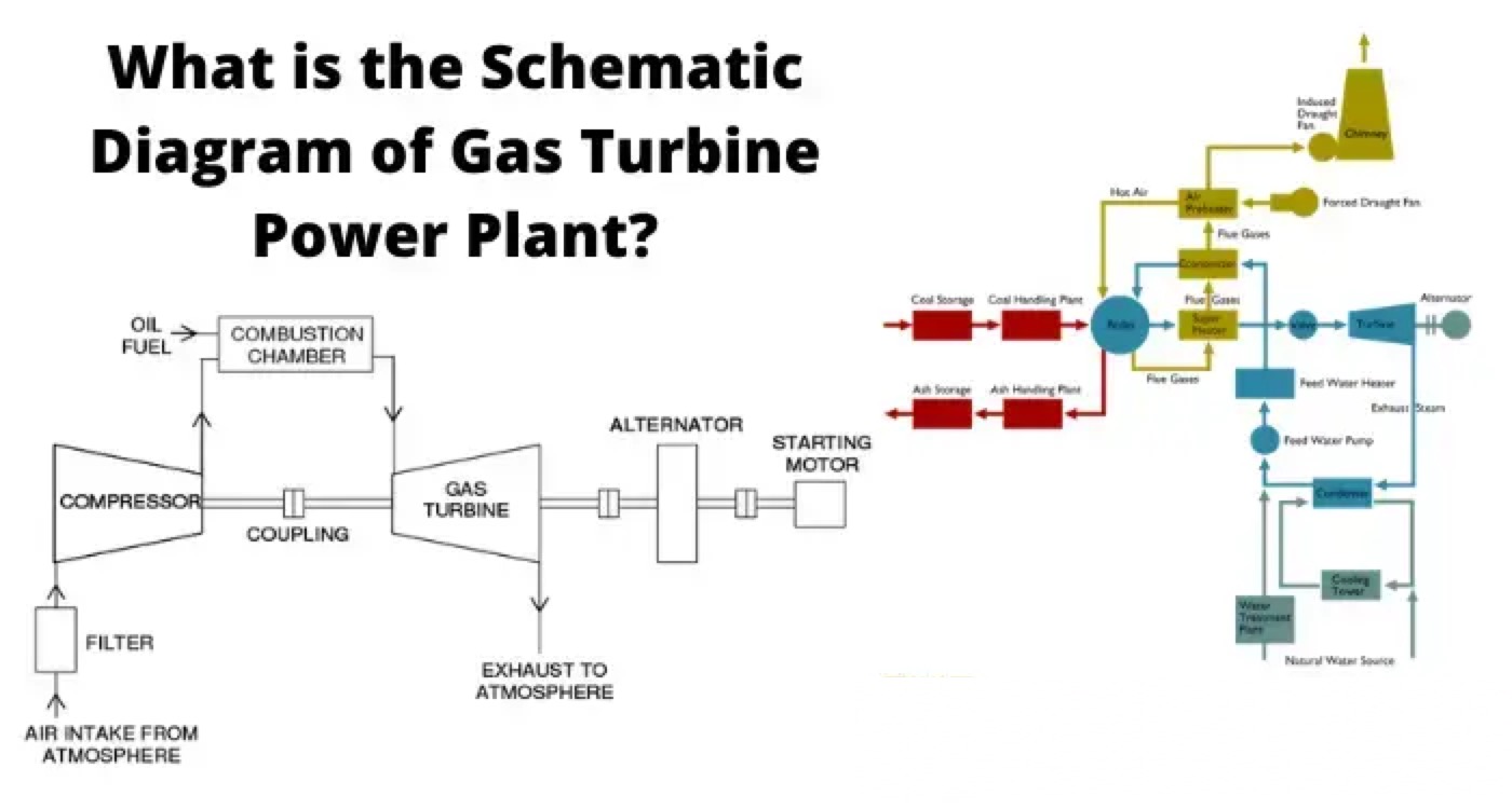
The main components of a gas turbine power plant are the

  1. compressor,

  2. regenerator,

  3. combustion chamber,

  4. gas turbine,

  5. alternator, and

  6. starting motor.

Compressor

Air compressor used in a gas turbine power plant is mainly of the rotary type. The air filter is attached at the inlet of the compressor where air gets filtered from dust. The rotary blades attached to the shaft push the air between stationary blocks, and consequently, the pressure of the air is increased. High pressure air is available at the outlet of the compressor.

Regenerator

There is always some heat presents in the exhaust gases in a gas turbine power plant. A portion of this heat is utilized in the regenerator. In regenerator, there is a net of fine tubes. The compressed air is passed through these fine tubes. The whole arrangement is enclosed in a vessel through which hot exhaust gases from turbine pass. During passing through the fine tubes, compressed air gets a portion of heat carried by exhaust gases. In this way, a significant portion of the heat of exhaust gases raises the temperature of the compressed air before it enters into the combustion chamber.

Combustion Chamber

After passing through the regenerator, the hot compressed air enters into the combustion chamber. In the combustion chamber, there are burners through which fuel oil is injected in the form of oil spray. Due to combustion of this hot oil spray inside the combustion chamber, the air attends a very high temperature. The temperature is about 3000oF. The compressed air mixed with combustion gases then cooled down to 1500oF to 1300oF before it is being delivered to the turbine for doing mechanical work there.

Schematic Diagram of Gas Turbine Power Plant

Alternator

The rotor of an alternator is attached to the same shaft of the turbine hence the alternator rotates along with the turbine and produces electrical energy.

Starting Motor

In gas turbine power plant the compressor, alternator, and turbine are attached to the same shaft. For starting the system, the compressor has to deliver pre-compressed air at starting. The shaft has to rotate to produce required compressed air for starting purpose. Hence, an alternative arrangement is required to run the compressor before the system is being started. This is done by a starting motor connected to the same shaft. A motor coupled with the main shaft supplies the required mechanical power for compressing air before starting.

Turbine

The compressed air mixed with combustion gases then enters in the turbine through nozzles. Here, the mixture of gases is suddenly expanded and it gains required kinetic energy to do mechanical work to rotate the turbine shaft (main shaft). In the turbine the temperature of the gases comes down to 900oF.

Statement: Respect the original, good articles worth sharing, if there is infringement please contact delete.

Give a tip and encourage the author!
Recommended
What Are the Types of Reactors? Key Roles in Power Systems
Reactor (Inductor): Definition and TypesA reactor, also known as an inductor, generates a magnetic field within the surrounding space when current flows through a conductor. Therefore, any current-carrying conductor inherently possesses inductance. However, the inductance of a straight conductor is small and produces a weak magnetic field. Practical reactors are constructed by winding the conductor into a solenoid shape, known as an air-core reactor. To further increase inductance, a ferromagnet
James
10/23/2025
35kV Distribution Line Single-Phase Ground Fault Handling
Distribution Lines: A Key Component of Power SystemsDistribution lines are a major component of power systems. On the same voltage-level busbar, multiple distribution lines (for input or output) are connected, each with numerous branches arranged radially and linked to distribution transformers. After being stepped down to low voltage by these transformers, electricity is supplied to a wide range of end users. In such distribution networks, faults such as phase-to-phase short circuits, overcurre
Encyclopedia
10/23/2025
Why Does MVDC Grounding Cause System Faults?
Analysis and Handling of DC System Grounding Faults in SubstationsWhen a DC system grounding fault occurs, it can be classified as single-point grounding, multi-point grounding, loop grounding, or reduced insulation. Single-point grounding is further divided into positive-pole and negative-pole grounding. Positive-pole grounding may cause misoperation of protection and automatic devices, while negative-pole grounding may lead to failure to operate (e.g., relay protection or tripping devices). On
Felix Spark
10/23/2025
MVDC: Future of Efficient, Sustainable Power Grids
The Global Energy Landscape Is Undergoing a Fundamental Transformation toward a "fully electrified society," characterized by widespread carbon-neutral energy and the electrification of industry, transportation, and residential loads.In today’s context of high copper prices, critical mineral conflicts, and congested AC power grids, Medium-Voltage Direct Current (MVDC) systems can overcome many limitations of traditional AC networks. MVDC significantly enhances transmission capacity and efficienc
Edwiin
10/21/2025
Send inquiry
Download
Get the IEE Business Application
Use the IEE-Business app to find equipment, obtain solutions, connect with experts, and participate in industry collaboration anytime, anywhere—fully supporting the development of your power projects and business.