1.Introduction
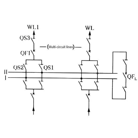
In a double-busbar system, line energizing/de-energizing and bus transfer are fundamental switching operations. Under the double-busbar configuration, line protection voltage is derived from busbar potential transformers (PTs). The PTs are connected to the busbar via primary disconnect switches, with their secondary windings routed to the PT secondary terminal box. Each PT has three secondary windings: one for protection and measurement, one for metering, and one open-delta winding. Except for the open-delta winding, the other two protection-related windings are all star-connected. These then feed into the PT paralleling panel and PT transfer panel (grounded via spark gaps in the terminal box), reaching terminal blocks from which voltage is distributed to various units.
The voltage switching box (located within the operating box) contains a voltage switching circuit that uses auxiliary contacts of the busbar-side disconnect switches to switch the voltage source from Bus III. On the voltage switching box, the LP lamp indicates the active busbar—i.e., from which busbar the voltage is being sourced. Both small busbar voltage circuits are connected to the voltage switching box; the system selects voltage from whichever busbar the line is currently connected to.
After opening or closing the busbar-side disconnect switch during operation, it is essential to verify that voltage switching has correctly occurred. Failure to do so may result in protection undervoltage or reverse energization from the PT secondary side. However, in actual field operations, operators often lack sufficient skill and perform incomplete or incorrect voltage switching checks, creating hidden risks for subsequent switching operations. The following provides a comprehensive analysis of methods for checking voltage switching during line de-energizing/energizing and bus transfer operations.
2. Analysis of Voltage Switching Verification Methods During Line De-energizing and Energizing in Double-Busbar Systems
2.1 Voltage Switching Check During Line De-energizing
The sequence for de-energizing a line is: open the circuit breaker → open the line-side disconnect switch → open the busbar-side disconnect switch. After opening the busbar-side disconnect switch, operators must verify voltage switching status.
From the monitoring perspective:
Three-phase voltages should read zero;
The “PT Loss of Voltage” indicator light should illuminate;
The “Protection Alarm” light should turn on;
The monitoring system should generate a “PT Loss of Voltage” message.
On-site checks should confirm:
The corresponding busbar LP lamp on the voltage switching box is off;
The indicator light for the relevant disconnect switch on the bus differential protection panel is off.
This confirms that voltage switching for the line has been properly disconnected.
2.2 Voltage Switching Check During Line Energizing
The energizing sequence is: close the busbar-side disconnect switch → close the line-side disconnect switch → close the circuit breaker.
After closing the busbar-side disconnect switch, monitoring personnel should verify:
Three-phase voltages match normal busbar voltage;
The “PT Loss of Voltage” light turns off;
The “Protection Alarm” light turns off;
The monitoring system reports “PT Loss of Voltage Reset.”
On-site checks should confirm:
The corresponding busbar LP lamp on the voltage switching box is lit;
The indicator light for the relevant disconnect switch on the bus differential protection panel is lit.
This confirms that voltage switching for the line has been successfully established.
3. Analysis of Voltage Switching Verification During Bus Transfer in Double-Busbar Systems
Bus transfer refers to switching lines or transformers from one busbar to another for operation or standby in a double-busbar substation. It includes “hot transfer” and “cold transfer.”
Cold transfer is performed when the line circuit breaker is in hot standby: first open one busbar-side disconnect switch, then close the other. This method is typically used during emergency handling.
Hot transfer follows the “close-before-open” principle: first close the target busbar-side disconnect switch, then open the original busbar-side disconnect switch.
After closing the new busbar-side disconnect switch:
Monitoring should confirm both disconnect switches are closed;
The “Voltage Switching Relay Simultaneously Energized” indicator light should illuminate;
The monitoring system should report the “Voltage Switching Relay Simultaneously Energized” event.
On-site checks should show:
Both busbar LP lamps on the voltage switching box are lit (indicating dual-bus connection);
The corresponding disconnect switch indicator on the bus differential protection panel is lit;
An “Abnormal Disconnector Status” light may appear.
This prevents protection undervoltage after opening the disconnect switch of the busbar to be taken out of service.
After opening the original busbar-side disconnect switch:
Monitoring should confirm that disconnect switch is in the open position;
The “Voltage Switching Relay Simultaneously Energized” light should turn off;
The monitoring system should report the reset of this signal.
On-site checks should confirm:
The LP lamp for the disconnected busbar on the voltage switching box is off;
The corresponding disconnect switch indicator on the bus differential protection panel is off.
This prevents reverse energization from the PT secondary side to the de-energized busbar.
Note: A PT acts as a voltage source with extremely low internal impedance. If the PT secondary side back-feeds the primary side, a very high voltage can be induced on the primary, and even a small primary current can cause a large secondary current. This may trip the secondary miniature circuit breaker (MCB) of the operating bus PT at best, or at worst cause maloperation of distance protection, or even endanger personnel and equipment.
4.Impact of Poor Contact in Busbar Disconnector Auxiliary Contacts in Double-Busbar Operation
4.1 Impact on Line Protection
Line protection voltage switching relies on auxiliary contacts of the busbar-side disconnector. Poor contact may cause loss of voltage to line protection.
4.2 Impact on Bus Differential Protection
Busbar disconnector auxiliary contacts are used as digital inputs in bus differential protection. Poor contact may create false differential current, affecting correct operation of the bus differential relay.
4.3 Impact on Breaker Failure Protection
Breaker failure protection initiation depends on voltage switching via these auxiliary contacts. Poor contact can impair correct operation of failure protection.
4.4 Impact on Five-Prevention (5P) System
Poor contact may cause incorrect position indication of the disconnector in the monitoring system, potentially disrupting normal operations.
5. Additional Considerations Based on Historical Issues in Voltage Switching Checks
5.1 Reversed Voltage Switching Wiring
After new commissioning or replacement of operating mechanisms, verify that the LP lamp on the voltage switching box matches the actual connected busbar. For example, cases have occurred where the disconnector was connected to Bus I, but the Bus II lamp was lit.
5.2 Reversed Disconnector Auxiliary Contacts
After new commissioning or mechanism replacement, confirm that the LP lamp status corresponds to the actual disconnector position. For instance, the disconnector was open but Bus II lamp was on, or closed but Bus II lamp was off.
5.3 Inadequate Voltage Switching Verification
Both monitoring and on-site teams must thoroughly check voltage switching during energizing/de-energizing. For example, during energizing of a newly commissioned line, after closing the busbar-side disconnector, on-site staff confirmed normal voltage switching, but monitoring personnel did not check voltage. Later, protection PT-break alarms failed to reset. Only after on-site reminder did monitoring notice zero three-phase voltage and persistent “PT Break” alarm. Investigation revealed that commissioning personnel had forgotten to restore a manually opened voltage slider.
6.Conclusion
For operating personnel, switching operations are never trivial—no moment or detail should be overlooked. Always think critically, inspect meticulously, and never ignore any anomaly.