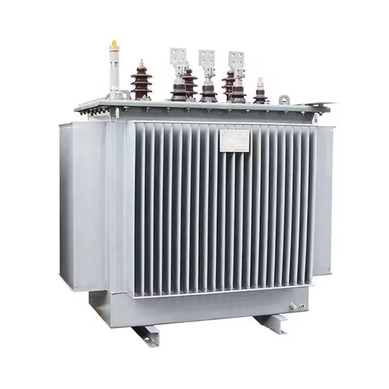
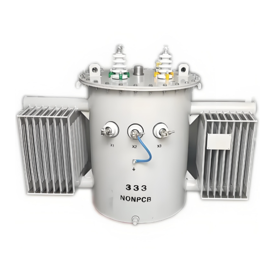
This guide comprehensively covers various aspects of distribution transformers. It delves into the construction elements, including the core, windings, cooling system, tank and cover, conservator, pressure relief device, Buchholz relay, silica gel breather, and winding temperature indicator. Additionally, it addresses topics such as transport, packing, and despatch processes, installation procedures, fittings and accessories, commissioning steps, as well as operation and maintenance guidelines.

The transformer should be situated in a well - ventilated area, shielded from excessive dust, corrosive fumes, and similar contaminants. Sufficient ventilation is crucial for the transformer tank and radiators to effectively dissipate heat. If the transformer is installed indoors, a clear space of approximately 1.25 meters should be maintained on all sides.
The foundation must be sturdy, level, and dry. In cases where rollers are installed, appropriate rails should be provided.
Necessary arrangements for oil draining, such as Oil Soak Pits, should be made in case of a fire. Fire separation walls should also be installed when deemed necessary.
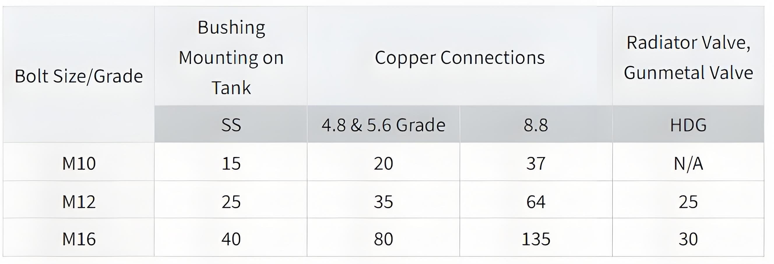
Components that were disassembled for transportation should be properly reassembled. The torque values (in Newton - meters) for various fastener sizes (nuts and bolts) are as follows:
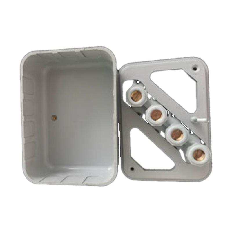
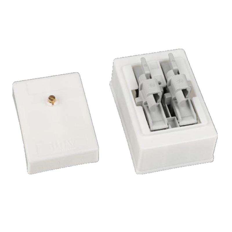
Clean the bushings and check for any fine cracks or other damages. Test the insulation resistance (IR) of each bushing with a 500V megger. The value should be no less than 100 megohms. Record the details of the bushings in the "Commissioning Report". Install all bushings and ensure that the test caps are tightened securely for reliable grounding.
Adjust the arcing horn gaps according to the requirements of insulation coordination.
If the MOG (presumably a specific component) is equipped with a locking lever, remove it. Install the conservator. In the case of an on - load tap changer (OLTC), its conservator may be provided separately or as a partitioned chamber within the main conservator. If the OLTC conservator is a separate component, it also needs to be installed.
Install the conservator as per the General Arrangement (G.A.) drawing. Usually, the small conservator for the on - load tap changer is connected to the main conservator.
Install the connecting pipe with Buchholz relay between the main tank and the conservator. Ensure the Buchholz relay is oriented correctly, with the arrow on it pointing towards the conservator.
Install the breather connecting pipes and silica gel breathers for both the main tank and the OLTC conservators.
When installing the flexi separator (air cell) inside the conservator, the following steps can be referred to: (Specific installation steps can be added here according to the actual content. Since no relevant content is provided in the original text, it can be further improved if there is relevant content later.)
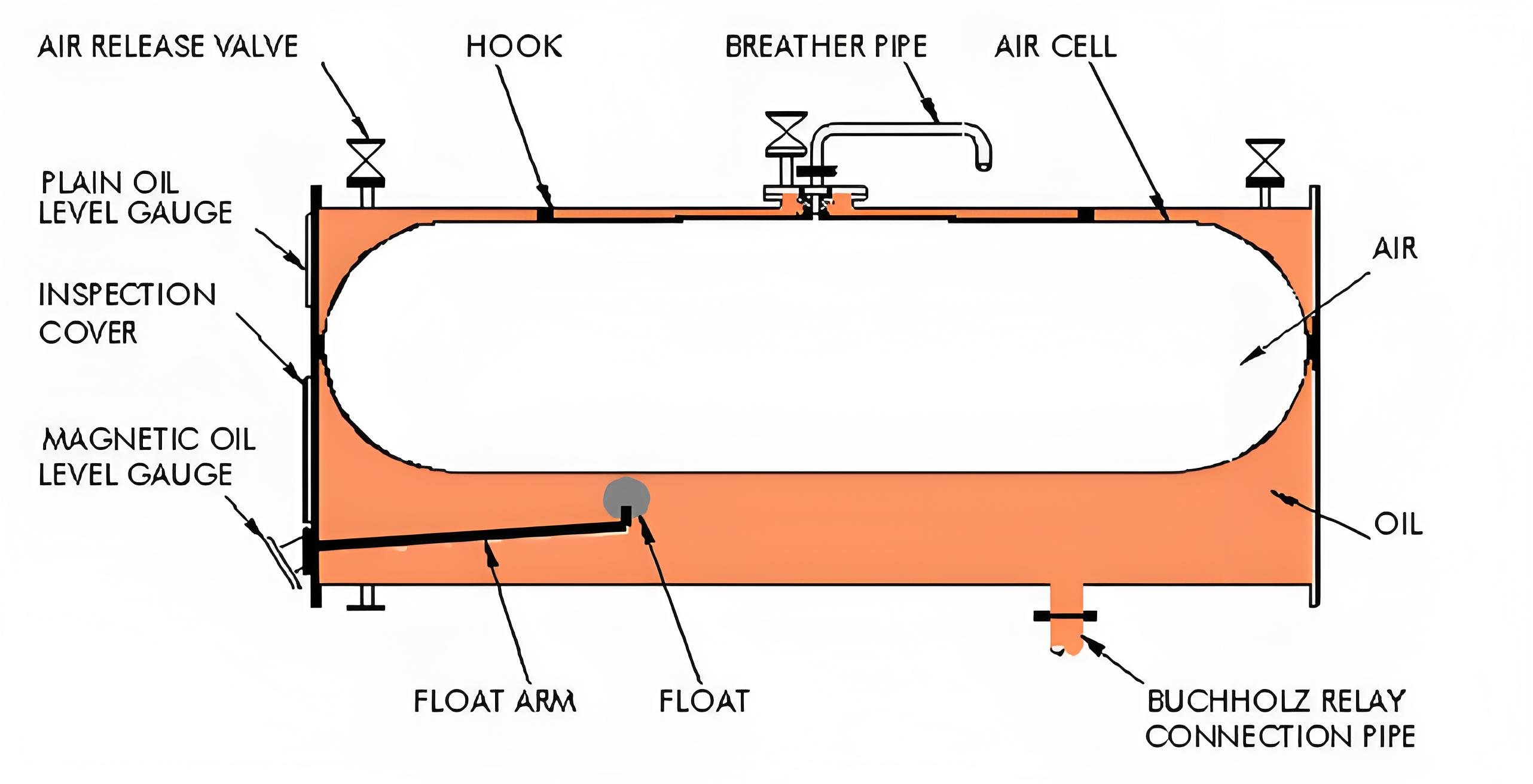
Install the air cell inside the conservator. Make sure the hooks on the air cell are properly engaged with the brackets inside the conservator.
Check for any leaks and ensure there is none.
The conservator with the air cell has been pressure - tested at the factory and dispatched under a slight positive pressure. Confirm that there is no oil leakage.
Install three air - release valves on the conservator.
Keep the air - release valves open. Attach the air - filling adapter to the breather pipe and inflate the air cell to the air pressure indicated on the instruction plate affixed to the transformer. Maintain this air pressure.
Open the air - release valves and start oil filling from the bottom filter valve of the transformer.
Monitor the air - release valves. As soon as oil starts to overflow, close the air - release valves one by one. Stop oil filling when all air - release valves are closed.
Remove the air - filling adapter.
Continue oil filling and observe the Magnetic Oil Level Gauge (MOLG).
Stop filling when the needle of the MOLG reaches the level corresponding to the ambient temperature during filling.
Install the silica - gel breather.
Do not open any of the air - release valves after oil filling is completed. If an air - release valve is opened, air will enter and the oil level will drop.
The ordinary oil - level gauge on the end - cover of the conservator should always indicate a full oil level.
If air enters the conservator, a drop in the oil level on the ordinary oil - level gauge will indicate it.
Regularly monitor the ordinary oil - level gauge.
With the separator installed, the conservator is positioned and connected above the transformer, and its lower part is linked to the oil - filling reserve via a pipe. Proceed as follows:
Create a vacuum inside the separator.
Using the same vacuum source, create a vacuum in the conservator.
Open the oil - filling valve of the transformer. Due to the vacuum in the conservator, the oil level will rise automatically.
Stop oil filling once the required volume is reached in the conservator.
While maintaining the vacuum in the conservator, allow dry air or nitrogen gas to enter the interior of the separator. The separator will then inflate on its own and occupy the free space, as the conservator is not completely full. During operation, in particular, the oil will rise to the top of the conservator.
Inflate the separator to the maximum level indicated on the instruction plate.
Check the vent holes and confirm that there is no residual air in the conservator. Adjust the oil level if necessary.
The floats of the Buchholz relay are tied up during transportation to prevent damage. They should now be released. Additionally, if a 'Test' lever is present, it should be set to the working position.
If an On - Load Tap Changer (OLTC) is provided, it may have its own separate breather.
Check that the color of the silica gel in the main breather is blue.
Remove the rubber cap that closes the breather pipe and the breather.
Fill oil in the oil cup and remove the seal that closes the breather opening.
Similarly, install the OLTC breather.
Radiators should be assembled one at a time. The oil required to fill the radiators is shipped separately in drums. Test an oil sample from each drum for Breakdown Voltage (BDV). Ensure it exceeds the minimum value specified in Indian Standard (I.S.) 1866 for new transformers.
If an oil filter machine is available, use it to fill the conservator completely with oil.
Clean the exterior of one radiator. Remove the blanking plates and clean the gaskets and radiator flanges. If the gaskets are damaged, replace them with spare gaskets.
If the blanking plates are not in place and there is suspicion that foreign material may have entered the radiators, clean their interiors by flushing with fresh and clean transformer oil.
Oil may seep through the tank - side radiator valves and be retained by the blanking plates. This oil should be collected in a clean container when removing the top and bottom blanking plates.
Align the radiator flanges with those on the tank. Ensure that the tank gasket is in position. Fasten them with bolts, nuts, spring washers, etc.
Use the operating handle to open the bottom radiator valve. Gradually unscrew the air - release plug on top of the radiator until air starts to escape.
Do not fully remove the air - release plug from its threads, as it will be difficult to control the oil flow. Close the air - release plug when oil flows steadily from it and no more air comes out.
Open the top radiator valve. The oil level in the conservator will now have dropped. Check for any oil leakage from the radiator itself and the gasket joints.
Restore the oil level and assemble the next radiator in the same manner.