Common Faults and Diagnostic Technologies of Oil-immersed Distribution Transformers

Vziman
08/07/2025

1.Common Faults and Diagnostic Measures

1.1 Transformer Oil Leakage

1.1.1 Oil Leakage from Tank Weld Seams

For oil leakage at flat joints, direct welding is applicable. For leakage at corners or joints reinforced with stiffeners, the exact leakage point is often difficult to locate, and re-leakage may occur after welding due to internal stress. For such cases, repair welding with an added iron plate is recommended: for two-surface joints, the iron plate can be cut into a spindle shape for welding; for three-surface joints, the iron plate should be cut into a triangular shape based on the actual configuration.

1.1.2 Bushing Oil Leakage

Bushing oil leakage is typically caused by bushing cracking or fractures, incorrect installation or aging of sealing gaskets, or loosening of the bushing clamping screws. If the first two conditions are present, replacement of the components is required; if the screws are loose, they should be re-tightened.

1.2 Multi-point Grounding of the Core

1.2.1 DC Current Surge Method

Disconnect the transformer core grounding wire and apply a DC voltage between the core and the tank for a short-duration high-current surge. Typically, 3–5 surges effectively burn off the unintended grounding points, significantly eliminating multi-point grounding faults.

1.2.2 Internal Inspection

For multi-point grounding caused by failure to flip or remove the positioning pin on the tank cover after installation, the pin should be flipped or removed. If the insulating paper between the clamp pad and the yoke has fallen off or been damaged, it should be replaced with new paper of appropriate thickness according to insulation specifications. If the clamp leg is too close to the core, causing bent laminations to touch it, adjust the clamp leg and straighten the bent laminations to ensure the required insulation clearance. Remove metallic foreign matter, particles, and impurities from the oil, clean oil sludge from all parts of the tank, and, if possible, perform vacuum drying on the transformer oil to remove moisture.

1.3 Overheating at Connections

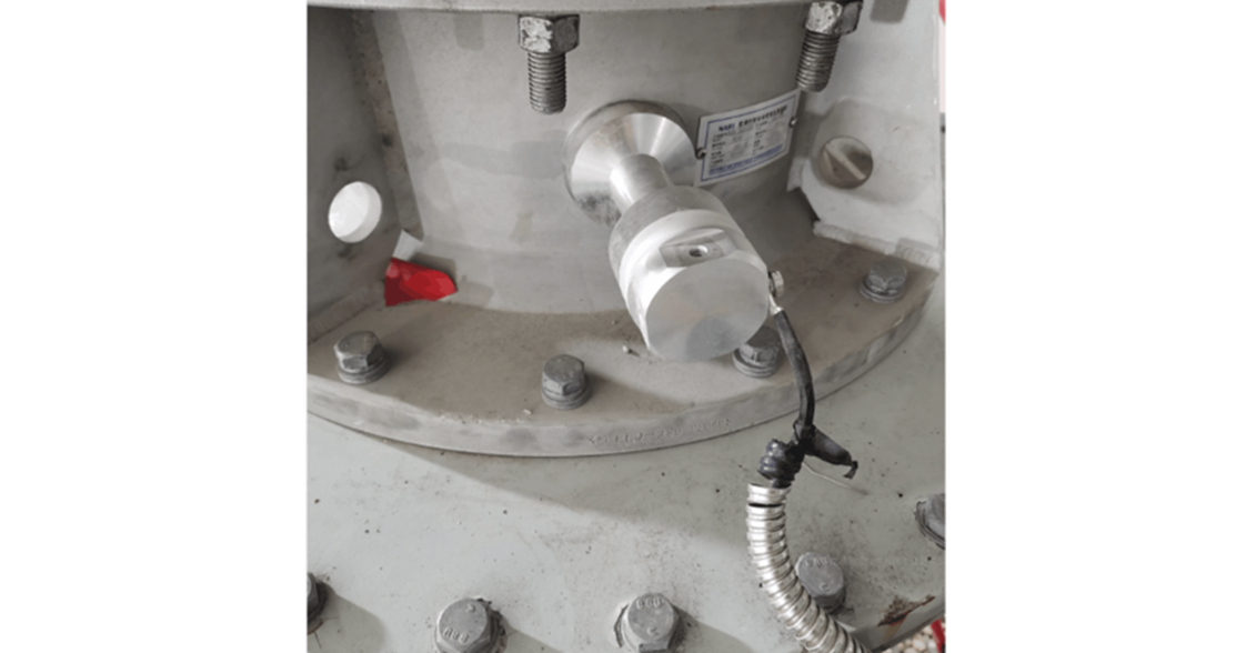
1.3.1 Connection of Conductive Rod Terminal

Transformer lead-out terminals are typically made of copper. In outdoor or humid environments, aluminum conductors must not be bolted directly to copper terminals. When moisture containing dissolved salts (electrolyte) infiltrates the contact surface between copper and aluminum, an electrochemical reaction occurs due to galvanic coupling, leading to severe corrosion of the aluminum. This rapidly damages the contact, causing overheating and potentially leading to serious accidents. To prevent this, direct copper-aluminum connections should be avoided.

2.Transformer Temperature Monitoring

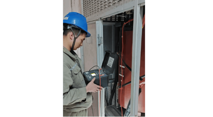
2.1 Infrared Thermography

Infrared thermography uses an infrared detector to capture the infrared radiation emitted by the target, amplifies and processes the signal, converts it into a standard video signal, and then displays the thermal image on a monitor. Localized overheating in the conductive circuit, caused by poor contact in transformer leads, overload operation, or core multi-point grounding, can be effectively detected using this method.

2.2 Oil Surface Temperature Indication

The oil surface temperature indicator monitors the temperature of the transformer oil, provides alarm signals when limits are exceeded, and initiates protective tripping when necessary.

3.Conclusion

In the 21st century, with increasing societal dependence on power systems and their continued expansion, fault diagnosis and condition-based maintenance of power transformers have become crucial measures for advancing the transformation of China’s power system and improving the scientific management of electrical equipment. These practices represent a key direction and focus for future development in power generation.

Vziman

Zhejiang Vziman Electric Group Co., Ltd. is a high-tech enterprise specializing in R&D, manufacturing, and service of power electrical equipment. Committed to innovation, quality, and customer satisfaction, it supplies smart solutions for global power sectors, covering grid construction, new energy, and industrial distribution. Core Business • Switchgear (GIS, circuit breakers, Recloser, Load break switch) • Distribution equipment (transformers, RMU, smart terminals) • Power automation systems • Engineering services (installation, maintenance, consulting) Technical Strength • Provincial R&D center, multiple patents • Modern production, ISO/GB/IEC/CE/UL certified • High capacity, large-scale delivery support Market & Vision Serves State Grid, Southern Grid, and global projects (Asia, Africa, Europe, etc.). Aims to lead in smart grids and new energy, promoting sustainable energy development.

Working Principle and Introduction of Rectifier Transformers
Working Principle of Rectifier TransformersThe working principle of a rectifier transformer is the same as that of a conventional transformer. A transformer is a device that converts AC voltage based on the principle of electromagnetic induction. Typically, a transformer consists of two electrically isolated windings—the primary and secondary—wound around a common iron core. When the primary winding is connected to an AC power source, the alternating current generates a magnetomotive
Ron
08/07/2025
Analysis of Interlocking Protection Circuit for Furnace Transformer
Currently, the company operates two electric arc furnace (EAF) transformers. The secondary voltage ranges from 121 V to 260 V, with a rated current of 504 A / 12,213 A. The high-voltage side has a total of eight tap positions, utilizing motor-driven off-circuit voltage regulation. The equipment is equipped with a reactor of corresponding capacity, connected in series to designated taps on the high-voltage side. These transformers have been in operation for over 20 years. Throughout this period,
Dyson
08/07/2025
Development of SG-Type Open Ventilated Dry Transformers (OVTD)
Prior to the 1960s, dry-type transformers primarily employed Class B insulation in open-ventilated designs, with the product model designated as SG. At that time, foil windings were not yet available, so low-voltage coils were typically constructed using multi-strand conductors in layered or spiral configurations, while high-voltage coils adopted a disc-type design. The conductors used were either double glass-fiber-wrapped wires or single glass-fiber-wrapped wires with alkyd enamel coating.Most
Vziman
08/06/2025
Analysis of the Causes of Light Gas Generation in Electric Furnace Transformers and Improvements
A 25 MVA electric arc furnace transformer at a certain company is an equipment imported from the former Soviet Union. It consists of three single-phase transformers, each rated at 8.333 MVA, with a connection group of D,d0. The primary voltage is 10 kV, and the secondary voltage ranges from 140 to 230.4 V. The tap-changing method is on-load tap changing with 21 steps (steps 11, 12, and 13 are combined as one step, totaling 23 positions). Each phase can be regulated independently, allowing separa
Felix Spark
08/06/2025
Inquiry
Download
IEE-Business is dedicated to serving the personnel in the global power industry.
Join IEE-Business, not only can you discover power equipment and power knowledge, but also canhnd like - minded friends!