• Product
  • Suppliers
  • Manufacturers
  • Solutions
  • Free tools
  • Knowledges
  • Experts
  • Communities
Search


Interfacing of a Stepper Motor

Encyclopedia
Encyclopedia
Field: Encyclopedia
0
China

Stepper Motor Definition

A stepper motor is a DC motor that moves in steps, with rotation speed dependent on the electrical signal rate.

4bf5256495d9f553efd1b39fe0e3efd9.jpeg

Components

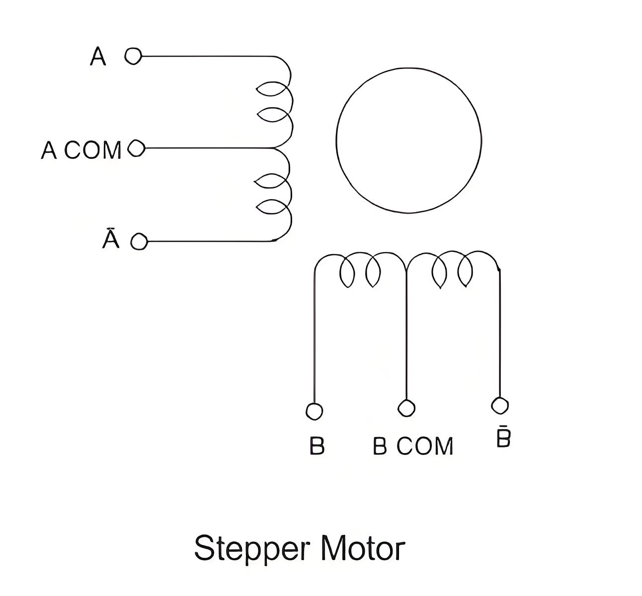
The motor has a rotor (permanent magnet) and a stator (winding), with the rotor rotating and the stator stationary.

Working Principle

The center tap on the stator winding allows current direction change when grounded. This changes the stator’s magnetic properties, selectively attracting and repelling the rotor to create a stepping motion.

Stepping Sequence

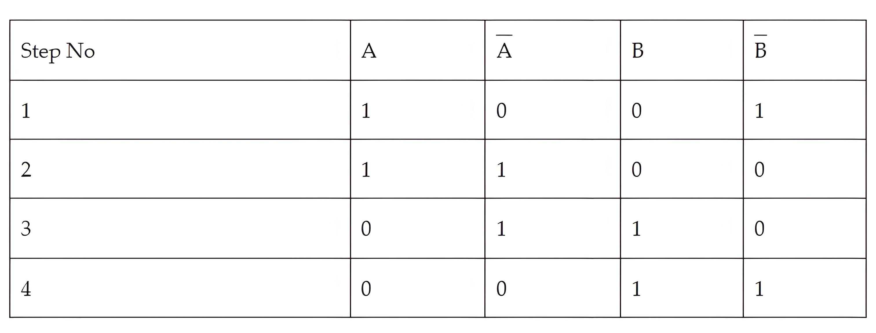
In order to get correct motion of the motor, a stepping sequence has to be followed. This stepping sequence gives the voltage that must be applied to the stator phase. Normally a 4 step sequence is followed.

When the sequence is followed from step 1 to 4, we get a clock wise rotation and when it is followed from step 4 to 1, we get a counter clockwise rotation.

ef15d3de898a16407f096c05b4daf9ba.jpeg

Interfacing Diagram

5f7c0a08ef19b54a4ba11809a5f2068a.jpeg

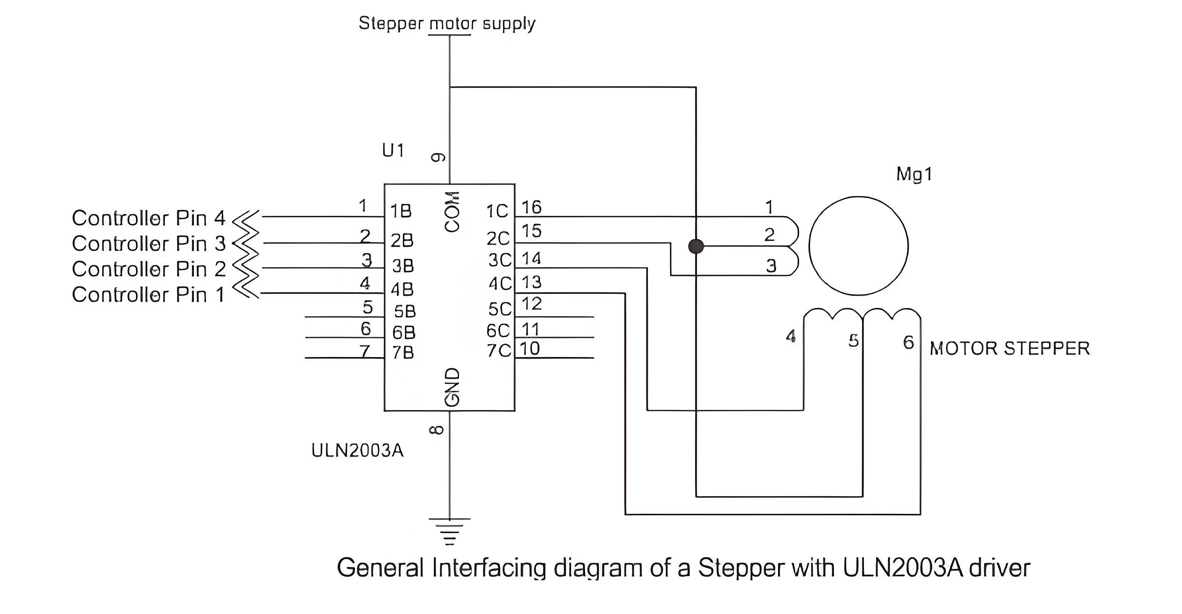
The diagram below shows the interfacing of stepper motor to a micro-controller. This is general diagram and can be applied to any micro-controller family like PIC micro-controller, AVR or 8051 micro-controller.

Since the microcontroller cannot provide enough current, a driver like ULN2003 is used to run the motor. Individual transistors or other driver ICs can also be used. Ensure external pull-up resistors are connected if needed. Never connect the motor directly to the controller pins. The motor voltage depends on its size.

A typical 4 phase uni-polar stepper motor has 5 terminals. 4 phase terminals and one common terminal of the center tap that is connected to ground. The programming algorithm for continuous rotation in clockwise mode is given below-

  • Initialize the port pins used for the motor as outputs

  • Write a common delay program of say 500 ms

  • Output first sequence-0 × 09 on the pins

  • Call delay function

  • Output second sequence-0 × 0 c on the pins

  • Call delay function

  • Output third sequence-0 × 06 on the pins

  • Call delay function

  • Output fourth sequence-0 × 03 on the pins

  • Call delay function

  • Go to step 3

Step Angle

The number of steps required to complete one full rotation depends on the step angle of the stepper motor. The step angle can vary from 0.72 degrees to 15 degrees per step. Depending on that 500 to 24 steps may be required to complete one rotation. In position control applications the selection on motor should be based on the minimum degree of rotation that is required per step.

Half Stepping

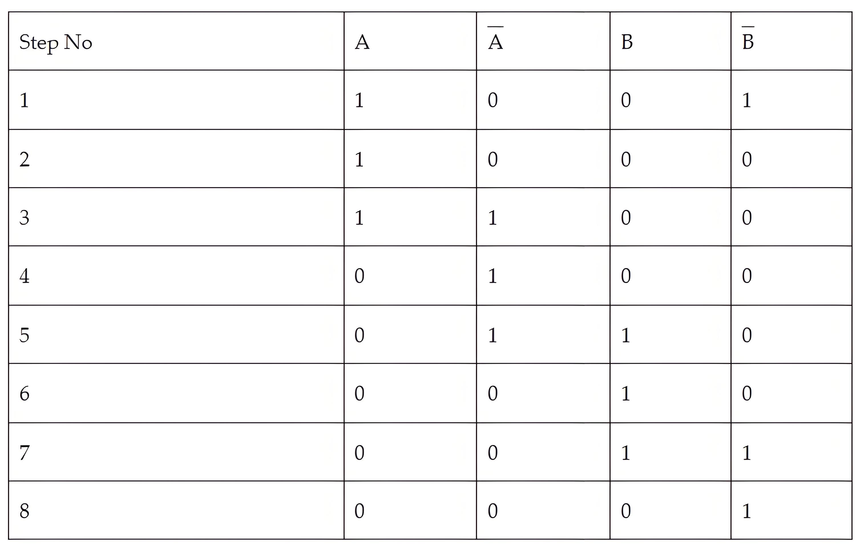
Stepper motors can operate at half the actual step angle, known as half stepping. For example, a motor rated for 15 degrees per step can be programmed to rotate at 7.5 degrees per step using a special half-stepping sequence.

e7884b1a34f89c1664a2af5f1a9c46ca.jpeg

Stepper Motor v/s Servo Motor

Both the stepper motor and servo motor are used primarily in position control applications. But there lies a difference in their working and construction. The stepper motor has a large number of poles or teeth on their rotor and these teeth act as magnetic north and south poles which gets attracted or repelled to the electrically magnetized coil of the stator. This helps in the stepping motion that a stepper generates.

On the other hand, in a servo motor the position is controlled by the specialized circuit and the feedback mechanism, which generates an error signal to move the motor shaft.

Give a tip and encourage the author!
Recommended
SST Technology: Full-Scenario Analysis in Power Generation, Transmission, Distribution, and Consumption
I. Research BackgroundPower System Transformation NeedsChanges in energy structure are placing higher demands on power systems. Traditional power systems are transitioning toward new-generation power systems, with the core differences between them outlined as follows: Dimension Traditional Power System New-Type Power System Technical Foundation Form Mechanical Electromagnetic System Dominated by Synchronous Machines and Power Electronic Equipment Generation-Side Form M
Echo
10/28/2025
SST Transformer Core Loss Calculation and Winding Optimization Guide
SST High-Frequency Isolated Transformer Core Design and Calculation Material Characteristics Impact:Core material exhibits varying loss behavior under different temperatures, frequencies, and flux densities. These characteristics form the foundation of overall core loss and require precise understanding of nonlinear properties. Stray Magnetic Field Interference:High-frequency stray magnetic fields around windings can induce additional core losses. If not properly managed, these parasitic losses
Dyson
10/27/2025
Design of a Four-Port Solid-State Transformer: Efficient Integration Solution for Microgrids
The use of power electronics in industry is increasing, ranging from small-scale applications such as chargers for batteries and LED drivers, to large-scale applications like photovoltaic (PV) systems and electric vehicles. Typically, a power system consists of three parts: power plants, transmission systems, and distribution systems. Traditionally, low-frequency transformers are used for two purposes: electrical isolation and voltage matching. However, 50-/60-Hz transformers are bulky and heavy
Dyson
10/27/2025
SST vs Traditional Transformer: Key Advantages
Solid-State Transformers (SST): The Future of Intelligent Power ConversionA solid-state transformer (SST), also known as a power electronic transformer (PET), is a static power conversion device that integrates power electronics, high-frequency transformation, and advanced control systems based on electromagnetic induction. It enables the conversion of electrical energy from one set of voltage, current, and frequency characteristics to another—while offering active control, bidirectional power f
Echo
10/27/2025
Send inquiry
Download
Get the IEE Business Application
Use the IEE-Business app to find equipment, obtain solutions, connect with experts, and participate in industry collaboration anytime, anywhere—fully supporting the development of your power projects and business.