The use of power electronics in industry is increasing, ranging from small-scale applications such as chargers for batteries and LED drivers, to large-scale applications like photovoltaic (PV) systems and electric vehicles. Typically, a power system consists of three parts: power plants, transmission systems, and distribution systems. Traditionally, low-frequency transformers are used for two purposes: electrical isolation and voltage matching. However, 50-/60-Hz transformers are bulky and heavy. Power converters are used to enable compatibility between new and legacy power systems, leveraging the concept of solid-state transformers (SST). By employing high- or medium-frequency power conversion, SSTs reduce transformer size and offer higher power density compared to conventional transformers.
Advancements in magnetic materials—featuring high flux density, high power and frequency capability, and low power losses—have enabled researchers to develop SSTs with high power density and efficiency. In most cases, research has focused on traditional dual-winding transformers. However, the growing integration of distributed generation, along with the development of smart grids and microgrids, has led to the concept of multi-port solid-state transformers (MPSST).
At each port of the converter, a dual active bridge (DAB) converter is used, which utilizes the transformer’s leakage inductance as the converter’s inductor. This reduces size by eliminating the need for additional inductors and also lowers losses. Leakage inductance depends on winding placement, core geometry, and coupling coefficient, making transformer design more complex. Phase shift control is used in DAB converters to regulate power flow between ports. However, in an MPSST, phase shift at one port affects power flow at other ports, increasing control complexity with the number of ports. As a result, most MPSST research focuses on three-port systems.
This paper focuses on the design of a solid-state transformer for microgrid applications. The transformer integrates four ports on a single magnetic core. It operates at a switching frequency of 50 kHz, with each port rated for 25 kW. The port configuration represents a realistic microgrid model comprising the utility grid, energy storage system, photovoltaic system, and local load. The grid port operates at 4,160 VAC, while the other three ports operate at 400 V.

Four-Port SST
Transformer Design
Table 1 shows various commonly used materials for manufacturing transformer cores, along with their advantages and disadvantages. The goal is to select a material capable of supporting 25 kW per port at a 50 kHz operating frequency. Commercially available transformer core materials include silicon steel, amorphous alloy, ferrite, and nanocrystalline. For the target application—a four-port transformer operating at 50 kHz with 25 kW per port—the most suitable core material must be identified. By analyzing the table, both nanocrystalline and ferrite are shortlisted as potential candidates. However, nanocrystalline exhibits higher power losses at switching frequencies above 20 kHz. Therefore, ferrite is ultimately selected as the core material for the transformer.

Different Core Materials and Their Characteristics
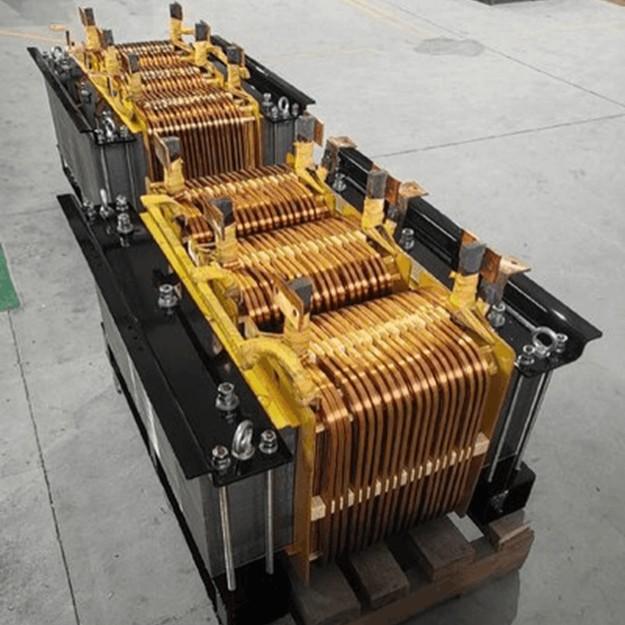
Transformer core design is also critical, as it affects compactness, power density, and overall size—but most importantly, it influences the transformer’s leakage inductance. For a 330-kW, 50-Hz dual-port transformer, core shapes such as core-type and shell-type have been compared, demonstrating that the shell-type configuration offers lower leakage inductance and smoother power flow. Therefore, a shell-type configuration will be used, with all four windings stacked concentrically on the center limb of the transformer, thereby improving the coupling coefficient.
The shell-type core measures 186×152×30 mm, and the ferrite material used is 3C94 in a 4xU93×76×30 mm configuration. Litz wire is used for winding both the medium-voltage (MV) and high-current ports, rated at 3.42 A and 62.5 A, respectively. For the low-voltage (LV) ports, 16 AWG and 4 AWG wires are employed. Twisting the LV windings together further enhances magnetic coupling.
After completing the proposed MV MPSST design, Maxwell-3D/Simplorer simulations are performed. The port voltages for the medium-voltage grid, energy storage, load, and photovoltaic systems are set to 7.2 kVDC and 400 VDC, respectively. Simulations are conducted under full load, with the load port delivering 25 kW at a switching frequency of 50 kHz and a 50% duty cycle. Power control is achieved by adjusting the phase shift between converter cells. Results are presented in the table. Different models exhibit varying characteristics such as core shape, cross-sectional area, loss, and volume. As shown in the table, Model 7 demonstrates lower leakage inductance and higher efficiency.

Model and Simulation Results
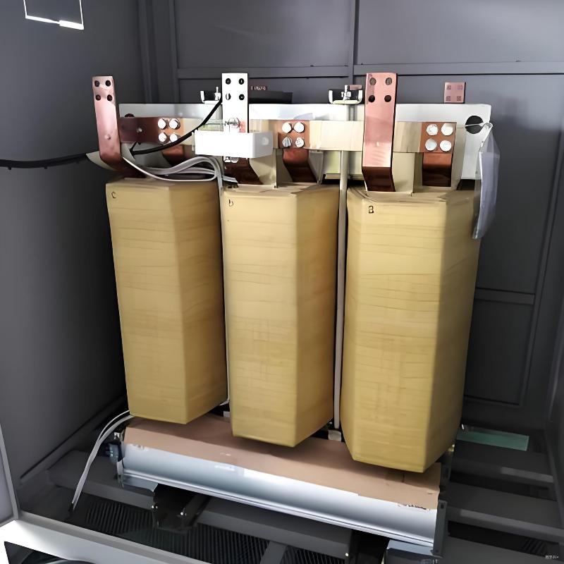
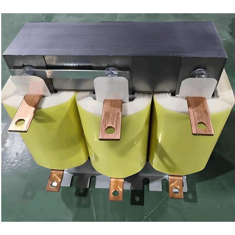
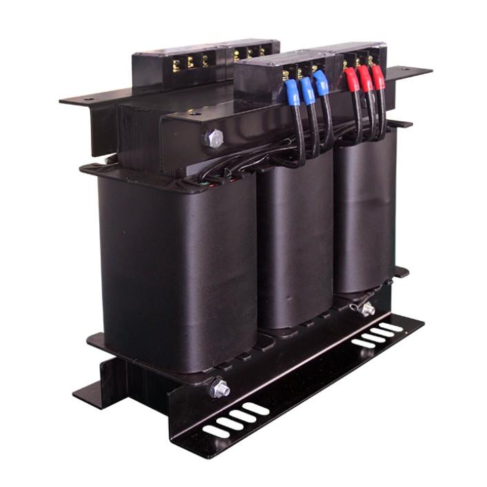
Experimental Setup
The core is constructed using four U-shaped cores assembled into one layer. The complete core consists of three layers with windings placed on the center limb. The three low-voltage (LV) port windings are wound together to enhance coupling. A dual active bridge (DAB) converter is designed to test the proposed transformer. SiC MOSFETs are used in the converter design. For the medium-voltage (MV) port, a rectifier bridge is implemented using SiC diodes, which is also connected to a resistive load bank rated to handle 7.2 kV.

Conclusion
This paper focuses on the design of a four-port medium-voltage multi-port solid-state transformer (MV MPSST) that enables the integration of four different sources or loads in microgrid applications. One port of the transformer is a medium-voltage (MV) port rated for 4.16 kV AC. Various transformer models and core materials were reviewed. In addition to the transformer design, test setups were developed for both the MV and LV ports. An efficiency of 99% was achieved in the experimental validation.