Why is it difficult to increase the voltage level?

The solid-state transformer (SST), also known as a power electronic transformer (PET), uses voltage level as a key indicator of its technological maturity and application scenarios. Currently, SSTs have reached voltage levels of 10 kV and 35 kV on the medium-voltage distribution side, while on the high-voltage transmission side, they remain in the stage of laboratory research and prototype validation. The table below clearly illustrates the current status of voltage levels across different application scenarios:
| Application Scenario | Voltage Level | Technical Status | Notes and Cases |
| Data Center / Building | 10kV | Commercial Application | There are many mature products. For example, CGIC provided a 10kV/2.4MW SST for the "East Digital and West Calculation" Gui'an Data Center. |
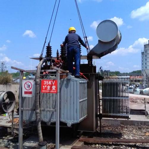
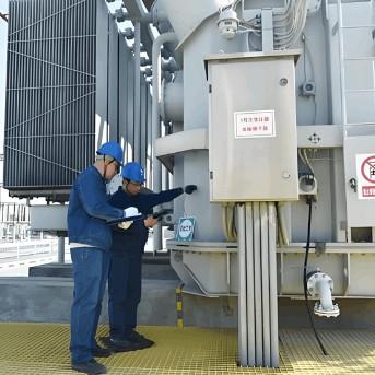
| Distribution Network / Park - level Demonstration | 10kV - 35kV | Demonstration Project | Some leading enterprises have launched 35kV prototypes and conducted grid - connected demonstrations, which is the highest voltage level known for engineering application so far. |
| Transmission Side of Power System | > 110kV | Laboratory Principle Prototype | Universities and research institutes (such as Tsinghua University, Global Energy Internet Research Institute) have developed prototypes with voltage levels of 110kV and even higher, but no commercial projects have been found so far. |
1. Why is it difficult to increase the voltage level?
The voltage level of a solid-state transformer (SST) cannot be simply increased by stacking components; it is constrained by a series of fundamental technical challenges:
1.1 Voltage withstand limitation of power semiconductor devices
This is the core bottleneck. Currently, mainstream SSTs use silicon-based IGBTs or more advanced silicon carbide (SiC) MOSFETs.
The voltage rating of a single SiC device is typically around 10 kV to 15 kV. To handle higher system voltages (e.g., 35 kV), multiple devices must be connected in series. However, series connection introduces complex "voltage balancing issues," where even minor differences between devices can lead to voltage imbalance and result in module failure.
1.2 Challenges in high-frequency transformer insulation technology
The core advantage of SSTs lies in size reduction through high-frequency operation. However, under high frequencies, the performance of insulation materials and electric field distribution become extremely complex. The higher the voltage level, the more stringent the requirements for insulation design, manufacturing processes, and thermal management of the high-frequency transformer. Achieving tens of kV-level high-frequency insulation within a limited space represents a significant challenge in materials and design.
1.3 Complexity of system topology and control
To handle high voltages, SSTs typically adopt cascaded modular topologies (e.g., MMC—Modular Multilevel Converter). The higher the voltage level, the greater the number of sub-modules required, leading to an extremely complex system structure. Control difficulty increases exponentially, and both cost and failure rate rise accordingly.
2. Future Outlook
Despite the significant challenges, technological breakthroughs continue:
Device advancement: Higher-voltage-rated SiC and gallium nitride (GaN) devices are under development and represent the foundation for achieving higher-voltage SSTs.
Topology innovation: New circuit topologies, such as hybrid approaches (combining conventional transformers with power electronic converters), are considered a viable path for rapid breakthroughs in high-voltage applications.
Standardization: As organizations like IEEE begin to establish SST-related standards, this will promote standardized design and testing, accelerating technological maturity.
3. Conclusion
Currently, 10 kV SSTs have entered commercial application, and the 35 kV level represents the highest level achieved in demonstration projects, while voltage levels of 110 kV and above remain in the realm of forward-looking technical research. The advancement of solid-state transformer voltage levels is a gradual process that depends on coordinated progress in power semiconductors, materials science, control theory, and thermal management technologies.
Recommended