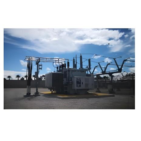
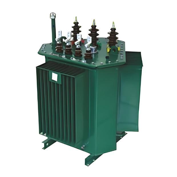
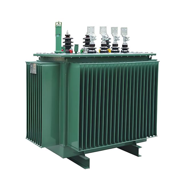
Commissioning Test Procedures for Oil-Immersed Power Transformers

Transformer Testing Procedures and Requirements
1. Non-Porcelain Bushing Tests
1.1 Insulation Resistance
Suspend the bushing vertically using a crane or support frame. Measure the insulation resistance between the terminal and the tap/french using a 2500V megohmmeter. The measured values should not significantly deviate from factory values under similar environmental conditions. For capacitive-type bushings rated 66kV and above with tap bushings, measure the insulation resistance between the "small bushing" and the flange using a 2500V megohmmeter. This value should not be less than 1000MΩ.
1.2 Dielectric Loss Measurement
Measure the tan delta (dissipation factor) and capacitance values of the main insulation to the tap using the positive wiring method, following the instrument's specified connections. Select a test voltage of 10kV. The high-voltage test leads for dielectric loss measurement should be suspended with insulating tape, kept away from other equipment and the ground, with proper safety precautions to prevent unauthorized entry into the high-voltage test area. The measured tan delta and capacitance values should not significantly differ from factory values and must comply with handover standards.
2. On-Load Tap-Changer Inspection and Testing
Inspect the complete action sequence of the on-load tap-changer contacts, measuring the transition resistance value and switching time. The measured transition resistance values, three-phase synchronization deviation, switching time values, and forward-reverse switching time deviation must all comply with the manufacturer's technical requirements.
3. DC Resistance Measurement of Windings with Bushings
Measure the DC resistance of the high-voltage winding at each tap position and the low-voltage side. For transformers with neutral points, it is recommended to measure single-phase DC resistance. Record the ambient temperature during measurement for conversion and comparison with factory values. The deviation between lines or phases should comply with handover standards.
4. Voltage Ratio Check of All Tap Positions
Connect the turns ratio tester leads to the high and low voltage sides of the three-phase transformer. Check the voltage ratio of all tap positions. Compared to the manufacturer's nameplate data, there should be no significant difference, and the ratios should follow expected patterns. At the rated tap position, the allowable error is ±0.5%. For three-winding transformers, perform ratio tests separately for high-medium, medium-low windings.

5. Check Three-Phase Connection Group and Polarity of Single-Phase Transformer Leads
The inspection results should match the design requirements, nameplate markings, and symbols on the transformer housing.
6. Insulating Oil Sampling and Testing
Oil sampling should only be conducted after the transformer has been fully filled with oil and allowed to stand for the specified time. After collecting oil samples, seal the containers properly and send them promptly to the relevant department for testing.
7. Insulation Resistance, Absorption Ratio or Polarization Index Measurement
All insulation-related tests should be conducted after the insulating oil has passed testing and during weather conditions with acceptable humidity. For transformers requiring polarization index measurement, verify that the megohmmeter short-circuit current is not less than 2mA. Record the test ambient temperature to enable conversion to the same temperature as factory tests for comparison. The results should not be less than 70% of factory values. Test items should include: high-(medium+low+ground), medium-(high+low+ground), low-(medium+high+ground), total-ground, core-(clamping+ground), and clamping-(core+ground). For example, for high-(medium+low+ground), short-circuit the three phases of the high-voltage side and the corresponding neutral point (if available), ground all other parts, connect the high-voltage terminal of the megohmmeter to the high-voltage side, and the ground terminal to ground for testing.
8. Measurement of tan delta (Dissipation Factor) of Windings with Bushings
Use the reverse wiring method for testing, following the instrument's specified connections. Test items should be conducted sequentially: high-(medium+low+ground), medium-(high+low+ground), low-(medium+high+ground), total-ground. During testing, suspend the high-voltage test leads of the tan delta tester with insulating tape, keeping them away from the transformer housing. Record the ambient temperature during testing. When converted to the same temperature as factory tests for comparison, the values should not exceed 1.3 times the factory values. If measurements significantly deviate from factory values, clean the bushings or use conductor shielding on the bushings to reduce surface leakage current. Measurements should preferably be conducted during weather with relatively low humidity.
9. DC Leakage Current Measurement of Windings with Bushings
Preferably read the leakage current at the high-voltage end. Test items should include: high-(medium+low+ground), medium-(high+low+ground), low-(medium+high+ground). Measurements should be taken during weather with low humidity, with ambient temperature recorded. Leakage current values must not exceed handover standard specifications.
10. Electrical Tests
10.1 Winding Deformation Test
For transformers rated 35kV and below, the low-voltage short-circuit impedance method is recommended. For transformers rated 66kV and above, the frequency response analysis method is recommended for measuring winding characteristic spectra.
10.2 AC Withstand Voltage Test
Perform AC withstand voltage tests at the transformer terminals using either externally applied power frequency voltage or induced voltage testing methods. Series resonance induced voltage testing is preferred when possible to reduce test equipment capacity requirements. Neutral points of transformers rated 110kV and above should undergo separate AC withstand voltage tests. Test voltage values should follow handover standards.
10.3 Long-Time Induced Voltage Test with Partial Discharge Measurement
For transformers rated 220kV and above, on-site long-time induced voltage tests with partial discharge measurement must be conducted during new installation. For 110kV transformers, partial discharge tests are recommended when insulation is suspect. These tests detect non-penetrating internal insulation defects in transformers.
10.4 Impact Closing Test at Rated Voltage
Follow requirements specified in the startup plan.
10.5 Phase Verification
Verify the transformer phase sequence, which must match the grid phase sequence.