1. Çavdarê Xerîdarê
1.1 Bina û Girîngkirina Tirberhêya Daneyê ya 35kV GIS
Tirberha daneyê ya ZX2 bi îzolekirina gaz hatine çêkerandin di mihayê 2011 de û di mihayê 2012 de bi xelasa ser wergera biguherin. Li her parçeya bus hatine têne girîngkirin du grup tirberhê daney (PTs). Du grup PT li parçeya yekem bus hatine dizayn kirin di navbera yek kabinet da ku pêncê wê 600 mm e. Tirberhê daneyên sêphas hatine dizajin di forma triangulêr de li derexetina kabinet.
Tirberhê daney bi qablanên kabîlê kurt hatine pêvekirin ji bo disconnectoran di camerê bus da ya kabinetê PT. Disconnectoran bi busê sêphas hatine pêvekirin bi wayên hewceyên dixebitandîn di camerê bus ên SF₆ li benda berjêrin. Bina busê li bendêra berjêrin hatine dikare kêfşana were vêjirin, û bus ne hatine têne pêvekirin proteksiyonê xasî. Kefşanan bus bi bo proteksiyonê back-up ya switchê guherandinê wergera biguherin.
1.2 Moda Operasyonê Pê Wateya Xerîdarê
Pê wateya xerîdarê, rêza elektrik hatiye becerandin:
Sistemê 220kV: Qiaoshi Line û Huishi Line hatine becerandin di paralel bi switchê bus tieyan.
Barê Transformerê Serok: Transformerê serok 1 hatine bar kirin 47 MW, û transformerê serok 2 hatine bar kirin 14 MW.
Sistemê 35kV: Unit A hatiye becerandin bi do bus û operasyonê divî. Generatorê 2, ku 30.5 MW bar kir, hatiye pêvekirin bi Bus II ya Unit A bi bus 1 ya Unit E, hot oil interconnection line switchgears 361 û 367, û hatiye becerandin di paralel bi transformerê serok 2.
1.3 Prosesê Xerîdarê
Precursorê Xeta
Xerîda Malpera
Têmal Kirin
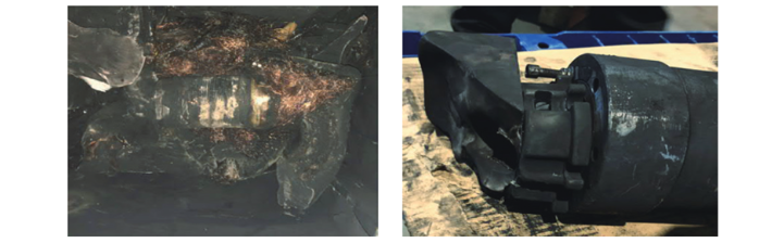
Derexet kabinet hatiye vegerandin. PT ya Phase A hatiye xerîda zor, û plugê Phase B hatiye kerdar. Malpera navendî hatiye şohandin.
Kablê yekemî yên cabinetê arrester hatiye xerîda. Testên pressure û insulation ya camerê bus hatiye normal.
2. Analizê Sedenê
2.1 Cî û Defektê Naxestinê û Destnaxistinê
2.2 Şertên Operasyonê Anormal
Faults Secondary Circuit
Overloading in the secondary circuit due to excessive parallel loops, resulting in increased heat generation according to \(Q = I²rt\).
Secondary short circuits triggering primary current surges and overheating.
System Overvoltage
Ferroresonance caused by switching operations or arcing grounding, generating overvoltages up to 2.5 times the rated value.
Waveform distortion accelerating insulation aging.
Three-Phase Imbalance
2.3 Analizê Naxestkirina Fabrikant
Ji Navbera Xeta
Analizê Stress
Non-flexible cable connections generated transverse stress concentrated at flange holes.
Fault progression: Intermittent grounding → Aluminum coating ablation → Fault reset → Final breakdown.
3. Plana Naxestkirina
3.1 Optimize Monitoring Equipment
3.2 Improve Structural Design
Cabinet Expansion: Increase cabinet width from 600 mm to 800 mm to improve heat dissipation.
Connection Upgrade: Replace short cable plugs with direct connections to reduce stress.
Modular Design: Adopt pluggable PTs/arresters to minimize maintenance time.
3.3 Enhance Protection System
Add dedicated circuit breakers for PT switchgears with overcurrent/overvoltage protection.
Install dedicated bus protection devices for rapid fault isolation.
Optimize zero-sequence circuit design to reduce resonance risk.
3.4 Adjust Operation and Maintenance Strategy
Establish full lifecycle management records for equipment, documenting installation and maintenance data.
Perform quarterly SF₆ moisture content tests with a threshold ≤300 ppm.
Conduct annual PT volt-ampere characteristic tests for comparison with factory data.
4. Lessons Learned and Preventive Measures
4.1 Key Lessons
Design Flaw: Co-location of PTs increased fault propagation risk.
Maintenance Gap: Failure to detect cumulative stress damage.
Protection Deficiency: Reliance on backup protection delayed fault clearance.
4.2 Preventive Measures
Strengthen equipment manufacturing supervision, focusing on insulation processes and structural integrity.
Promote condition-based maintenance using vibration monitoring to assess stress levels.
Revise design specifications to mandate flexible connections between PTs and buses.
Conduct anti-accident drills to standardize emergency response procedures for PT faults.
4.3 Implementation Results
Post-retrofit data shows:
Partial discharge reduced from 80 pC to 15 pC.
Temperature rise under full load decreased by 12°C.
Fault response time shortened from 600 ms to 40 ms.
5. Conclusion
This accident revealed multiple hidden risks in GIS equipment design, installation, and maintenance. Through structural optimization, protection system upgrade, and management enhancement, a comprehensive risk prevention system has been established. Continuous monitoring of equipment performance will provide replicable retrofit experience for similar substations.


