
Karon, ang karamihan sa mga secondary equipment sa bag-ong gipatayong mga intelligent substation gisulod sa mga prefabricated cabin nga anaa sa switchgear area. Human sa pagprokeso sa mga cabin body, ang mga manufacturer sa secondary equipment moadto sa mga cabin aron makahimo og installation ug debugging, resulta sa usa ka komplikado ug higantohanong proseso sa pagtukod. Ang tipikal nga 220 kV intelligent substation kasagaran nanginahimo og duha ka prefabricated cabin: usa para sa 220 kV ug usa para sa 110 kV. Ang tanang cabin adunay Type II, nga may sukat nga 6200mm×2800mm×3300mm. Ang Type II cabin makapuede mag-accommodate og 19 switchboards nga may sukat nga 800mm×600mm×2260mm, resulta sa isang ka baho nga rate sa paggamit sa espasyo sa loob sa cabin.
Arong masolusyonan ang prominent nga mga problema sa proseso sa pagtukod sa prefabricated cabin model sa intelligent substations, gi-propose kini sa paper ang pag-adopt sa rack-type prefabricated cabin model. Ang kabuok nga disenyo sa prefabricated cabin gibuno gikan sa aspetos sama sa pag-optimize sa struktura sa cabin, pag-arrange sa mga equipment sa loob sa cabin, ug pag-route sa optical ug electrical cables, ang layo mao ang pagbawas sa construction period ug pag-improve sa efficiency sa paggamit sa espasyo.
1. Hierarchical Nested Rack Structure Scheme
Sa disenyo sa rack-type structure, ang load-bearing structure sa secondary equipment gitangi isip usa ka integral bahin sa struktura sa prefabricated cabin body. Sa kabuok nga konteksto sa struktura sa cabin body, gipagtuman ang top-down hierarchical design.
1.1 Nested Installation Structure
Sa unang layer, nahimong importante ang prefabricated cabin body gihimo gikan sa hot-rolled section steel ug nabuo pinaagi sa integral welding, ang direkta nga pag-install sa rectangular sheet-like vertical components sa loob sa prefabricated cabin mahimong malipayog sa accuracy sa pag-install sa rack, wala na maayo alang sa implementasyon sa proyekto. Kini nga eskuema, sa panahon sa proseso sa pagprokeso sa prefabricated cabin, ang basic frame sa rack structure gipasabot sa loob sa cabin, isip gipakita sa Figure 1.
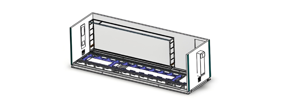
Figure 1 Schematic diagram of the installation components for the rack-mounted structure foundation
Ang mga basic installation components gihimo pinaagi sa CNC machines pinaagi sa sheet metal processing, naghatag og precise control sa dimensions ug naghatag og matigas nga pundasyon alang sa pag-install sa rack units. Tungod sa dako nga sukat sa mga basic installation components, ang pag-install sa frame sa loob sa cabin gibuno sa parehas sa proseso sa pagprokeso sa prefabricated cabin body.
1.2 The Second Layer of the Nested Installation Structure
Isip ang mid-layer sa pag-install sa rack, kini nga installation component makapuede mag-share sa core functional modules sa kaliwa ug kanan. Ipadayon usab kini ang fire isolation sa mga equipment.
1.3 The Third Layer of the Nested Installation Structure
Sa rack bearing unit, ang single-bay protection devices, measurement and control devices, switches, terminal blocks, buttons, ug uban pa, gipasabot. Ang mga butang kini wiran ug debugged isip usa ka independent module, forming a self-contained rack functional unit, isip gipakita sa Figure 2.

Figure 2 Schematic diagram of the rack functional unit
Ang production, installation, ug debugging sa rack parallel processes sa production ug installation sa cabin mismo, wala na makaapekto sa construction schedules. Kini nag-transform totally sa previous production mode diin ang switchboard-type structures required in-cabin wiring, significantly enhancing the efficiency of wiring in prefabricated cabins.
Human sa pag-install sa tanang equipment, ang iba't ibang devices sa rack giconnect pinaagi sa upper ug lower wire troughs nga horizontal nga running through the rack, enabling seamless interconnection of the in-cabin equipment. Moreover, ang wire troughs sa loob sa rack nagform og grid-like structure, allowing various devices between racks to be connected via this grid-shaped wiring system.
Human sa pag-complete sa tanang wiring ug debugging sa equipment sa loob sa rack, ang top cover, side cover plates, ug front cover plates sa rack gipasabot, isip gipakita sa Figure 3.
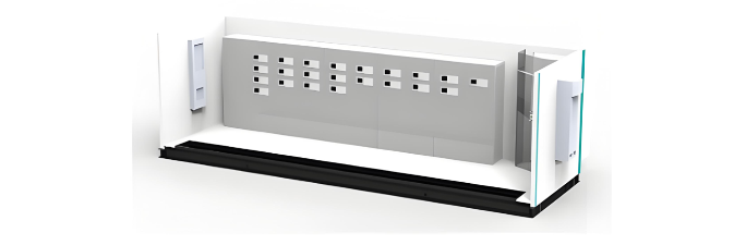
Figure 3 Effect drawing of the completed rack installation
Ang equipment sa loob sa rack sa prefabricated cabin arranged in an offset manner. Kini nga article gipili ang 220 kV line protection and measurement and control unit isip ehempiyo aron ilhustrar ang layout sa 220 kV rack equipment framework.
2. Design of the Standardized Scheme for Equipment Arrangement within the Rack of the Prefabricated Cabin
As shown in Figure 4, according to the configuration requirements of a 220 kV substation in the equipment installation area, for a single bay, it is necessary to configure two protection devices, one measurement and control device, two buttons, and several terminal blocks. Vertical wire troughs are installed in the wiring area, and locking buckles are configured to prevent accidental operations.
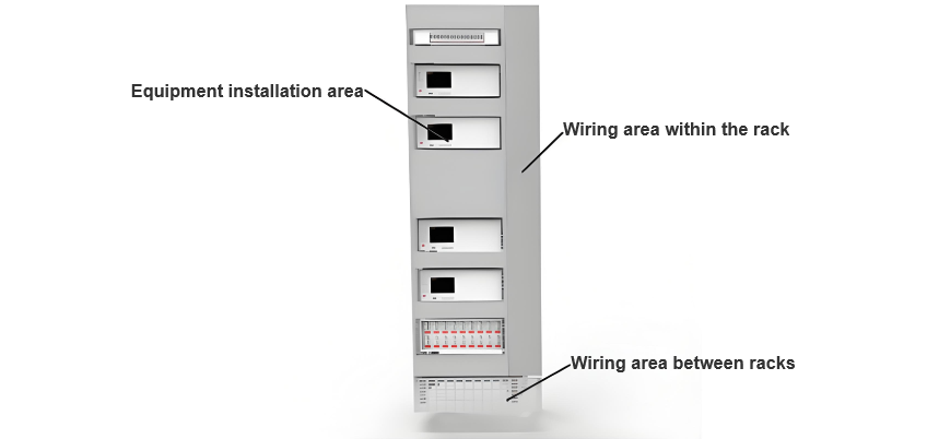
Figure 4 Schematic diagram of the device layout
3. Design of Cable Laying Scheme
3.1 Separate Routing of Optical and Electrical Cables
The dimensions of the rack remain 2260 (height) × 700 (width) × 600 (depth) mm. A wire trough with a height of approximately 40 mm is installed beneath each layer of equipment. Optical and electrical cables are routed separately, and all cables are laid out in a classified and zoned manner. As depicted in Figures 5 and 6, fiber optic jumpers are arranged on the left-hand side of the channel, while electrical cables are positioned on the right. Cables on the same side are bundled and placed together according to the installation positions of the devices.
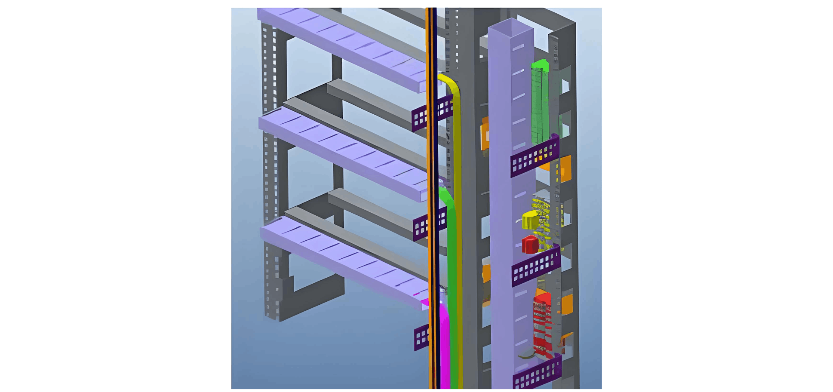
Figure 5 Schematic diagram of optical cable split-fiber layout
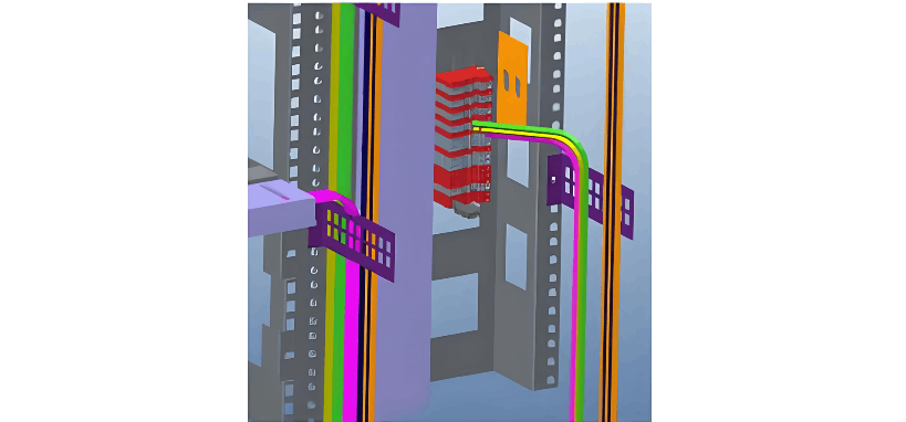
Figure 6 Schematic diagram of cable layout
3.2 Installation of a Centralized Transfer Rack
A centralized transfer rack for prefabricated optical cables, 700 mm wide, is installed inside the cabin. It is used to facilitate the connection between prefabricated optical cables and patch cables. The rack adopts a 40U installation framework, with the transfer boxes installed inside the framework, leaving sufficient space for the layout of front-end prefabricated optical cables and patch cables. Outdoor optical cables are converted into patch cables through the transfer cabinet. These patch cables are then transformed into fiber optic jumpers via the optical distribution frames within each cabinet and connected to various devices, thus completing the optical cable connection process. An inlet/outlet for the cable channel, which is connected to the station's cable trench, is provided inside the cabin.
4. Conclusions
The prefabricated cabin adopts a hierarchical nested rack structure. The framework is composed of several rack units, enabling the nested cabinets and the cabin body to be manufactured simultaneously and independently, which significantly improves construction efficiency.
The devices within the rack are functionally zoned, standardizing the arrangement of equipment inside the cabin.
Optical and electrical cables inside the prefabricated cabin adopt a bottom-routing method. The bottom of the cabin is arranged in layers, and wire trough boxes are installed beneath the switchboards, achieving the separation of optical and electrical cables.


