
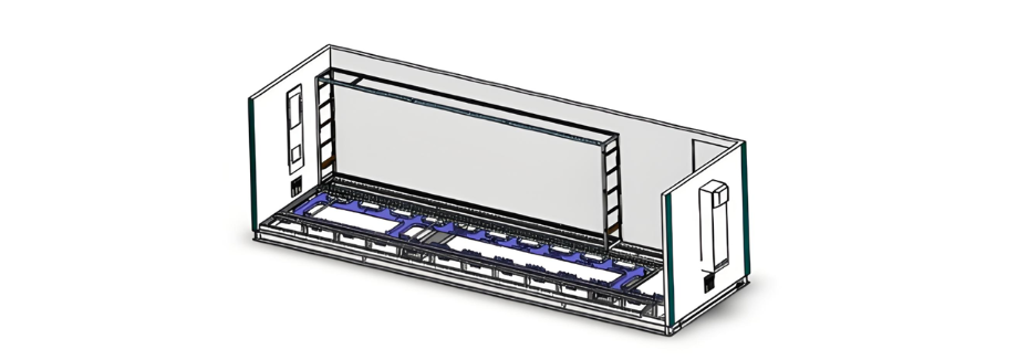
Այսպիսով, նոր կառուցված ինտելեկտական ենթակայանների մեծ մասը դրանք գտնվում են կանխահարկ դաշտային կայաններում, որոնք գտնվում են փոխանցման զոնայում։ Կայանների մարմինները պատրաստվելուց հետո երկրորդական iết bị sản xuất nhà sản xuất vào cabin để lắp đặt và thử nghiệm, dẫn đến quy trình xây dựng khá phức tạp và rườm rà. Một trạm biến áp thông minh tiêu chuẩn 220 kV thường yêu cầu lắp đặt hai cabin tiền chế: một cho 220 kV và một cho 110 kV. Cả hai cabin đều thuộc loại II, với kích thước 6200mm×2800mm×3300mm. Cabin loại II có thể chứa 19 tủ điện với kích thước 800mm×600mm×2260mm, dẫn đến tỷ lệ sử dụng không gian bên trong cabin thấp.
1. Համակարգային ներդրված սալային կառուցվածքի սխեմա
Սալային կառուցվածքի դիզայնի դեպքում երկրորդական սարքավորումի բեռնավորման կառուցվածքը դիտարկվում է որպես կանխահարկ կայանի մարմնի կառուցվածքի ինտեգրալ մաս: Կայանի մարմնի կառուցվածքի ընդհանուր համատեքստում կատարվում է վերևից ներքև հիերարխիկ դիզայն:
1.1 Ներդրված տեղադրման կառուցվածք
Առաջին շերտում, հաշվի առնելով, որ կանխահարկ կայանի մարմինը կազմված է ջերմ շարունակ սեկցիայի ստալի և ամբողջական կլանումով, կայանի ներսում ուղղանկյունաձև սալային ուղղահայաց բաղադրիչների ուղղակի տեղադրումը կունենա նշանակալի ազդեցություն սալայի տեղադրման ճշգրտության վրա, որը նպաստում չէ նախագծի իրականացմանը: Այսպիսով, այս սխեմայում կանխահարկ կայանի պատրաստման գործընթացում կայանի ներսում տեղադրվում է սալայի կառուցվածքի հիմնական շերտը, ինչպես ցուցադրված է նկար 1-ում:
Նկար 1 Սալային կառուցվածքի հիմքի տեղադրման բաղադրիչների սխեմա
Այս հիմնական տեղադրման բաղադրիչները պատրաստվում են CNC մեքենաներով սալայի մշակման միջոցով, որը lehetővé teszi a dimenziók pontos ellenőrzését és alapjaat adja a rack egységek telepítésének. Mivel az alapvető telepítési elemek méretei viszonylag nagyok, a keret belső telepítése megtörténik a prefabricált kabin szárnyának gyártása során.
1.2 A beágyazott telepítési szerkezet második szintje
A rack telepítés középső rétegeként ez a telepítési elem megosztható a bal és jobb oldali alapfunkcionális modulok között. Szintén tűzkülönítő célokat is szolgál a berendezések esetében.
1.3 A beágyazott telepítési szerkezet harmadik szintje
A rack terhelési egységen egy bájós védelmi eszközök, mérési és irányítási eszközök, kapcsolók, végpont blokkok, gombok stb. települnek. Ezek a komponensek független modulként lesznek beszabadítva és hibaelhárításra kerülnek, ami önmagában tartalmazó rack funkcionális egységet alkot, amelyet a 2. ábra illusztrál.

Figure 2 Schematic diagram of the rack functional unit
The production, installation, and debugging of the rack are parallel processes to the production and installation of the cabin itself, without affecting each other's construction schedules. This completely transforms the previous production mode where switchboard - type structures required in - cabin wiring, significantly enhancing the efficiency of wiring in prefabricated cabins.
After all equipment is installed, various devices within the rack are connected through the upper and lower wire troughs that run horizontally through the rack, enabling seamless interconnection of the in - cabin equipment. Moreover, the wire troughs inside the rack form a grid - like structure, allowing various devices between racks to be connected via this grid - shaped wiring system.
Once all the wiring and debugging of the equipment within the rack are completed, the top cover, side cover plates, and front cover plates of the rack are installed, as depicted in Figure 3.
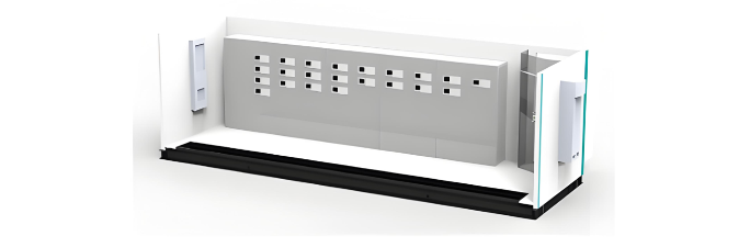
Figure 3 Effect drawing of the completed rack installation
The equipment within the rack of the prefabricated cabin is arranged in an offset manner. This article takes a 220 kV line protection and measurement and control unit as an example to illustrate the layout of the 220 kV rack equipment framework.
2. Design of the Standardized Scheme for Equipment Arrangement within the Rack of the Prefabricated Cabin
As shown in Figure 4, according to the configuration requirements of a 220 kV substation in the equipment installation area, for a single bay, it is necessary to configure two protection devices, one measurement and control device, two buttons, and several terminal blocks. Vertical wire troughs are installed in the wiring area, and locking buckles are configured to prevent accidental operations.
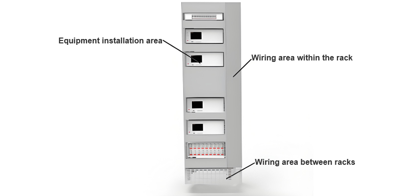
Figure 4 Schematic diagram of the device layout
3. Design of Cable Laying Scheme
3.1 Separate Routing of Optical and Electrical Cables
The dimensions of the rack remain 2260 (height) × 700 (width) × 600 (depth) mm. A wire trough with a height of approximately 40 mm is installed beneath each layer of equipment. Optical and electrical cables are routed separately, and all cables are laid out in a classified and zoned manner. As depicted in Figures 5 and 6, fiber optic jumpers are arranged on the left - hand side of the channel, while electrical cables are positioned on the right. Cables on the same side are bundled and placed together according to the installation positions of the devices.
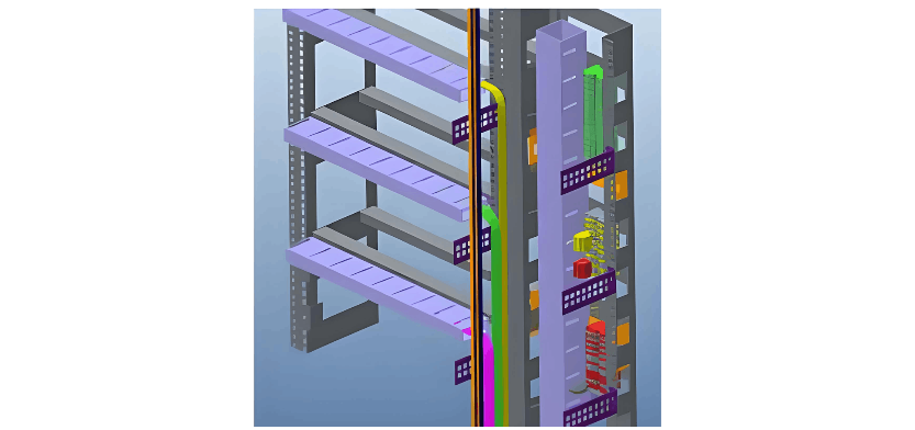
Figure 5 Schematic diagram of optical cable split-fiber layout
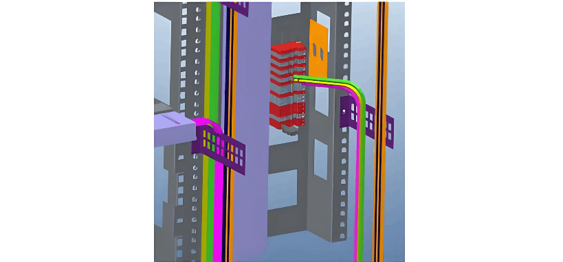
Figure 6 Schematic diagram of cable layout
3.2 Installation of a Centralized Transfer Rack
A centralized transfer rack for prefabricated optical cables, 700 mm wide, is installed inside the cabin. It is used to facilitate the connection between prefabricated optical cables and patch cables. The rack adopts a 40U installation framework, with the transfer boxes installed inside the framework, leaving sufficient space for the layout of front - end prefabricated optical cables and patch cables. Outdoor optical cables are converted into patch cables through the transfer cabinet. These patch cables are then transformed into fiber optic jumpers via the optical distribution frames within each cabinet and connected to various devices, thus completing the optical cable connection process. An inlet/outlet for the cable channel, which is connected to the station's cable trench, is provided inside the cabin.
4. Conclusions
The prefabricated cabin adopts a hierarchical nested rack structure. The framework is composed of several rack units, enabling the nested cabinets and the cabin body to be manufactured simultaneously and independently, which significantly improves construction efficiency.
The devices within the rack are functionally zoned, standardizing the arrangement of equipment inside the cabin.
Optical and electrical cables inside the prefabricated cabin adopt a bottom - routing method. The bottom of the cabin is arranged in layers, and wire trough boxes are installed beneath the switchboards, achieving the separation of optical and electrical cables.


