
Currently, most secondary equipment in newly - built intelligent substations is placed inside prefabricated cabins located in the switchgear area. After the cabin bodies are manufactured, secondary equipment manufacturers enter the cabins for installation and debugging, resulting in a rather complex and cumbersome construction process. A typical 220 kV intelligent substation usually requires the setup of two prefabricated cabins: one for 220 kV and one for 110 kV. Both cabins are of Type II, with dimensions of 6200mm×2800mm×3300mm. A Type II cabin can accommodate 19 switchboards with dimensions of 800mm×600mm×2260mm, leading to a low space utilization rate inside the cabin.
To address the prominent issues in the construction process of the prefabricated cabin model for intelligent substations, this paper proposes the adoption of a rack - type prefabricated cabin model. The overall design of the prefabricated cabin is carried out from aspects such as optimizing the cabin structure, arranging the equipment inside the cabin, and routing the optical and electrical cables, aiming to reduce the construction period and improve the space utilization efficiency.
1. Hierarchical Nested Rack Structure Scheme
In the design of the rack - type structure, the load - bearing structure of the secondary equipment is regarded as an integral part of the prefabricated cabin body structure. Under the overall context of the cabin body structure, a top - down hierarchical design is implemented.
1.1 Nested Installation Structure
At the first layer, considering that the prefabricated cabin body is made of hot - rolled section steel and formed by integral welding, directly installing rectangular sheet - like vertical components inside the prefabricated cabin would have a significant impact on the installation accuracy of the rack, which is not conducive to project implementation. Therefore, in this scheme, during the manufacturing process of the prefabricated cabin, a basic frame of the rack structure is installed inside the cabin, as shown in Figure 1.
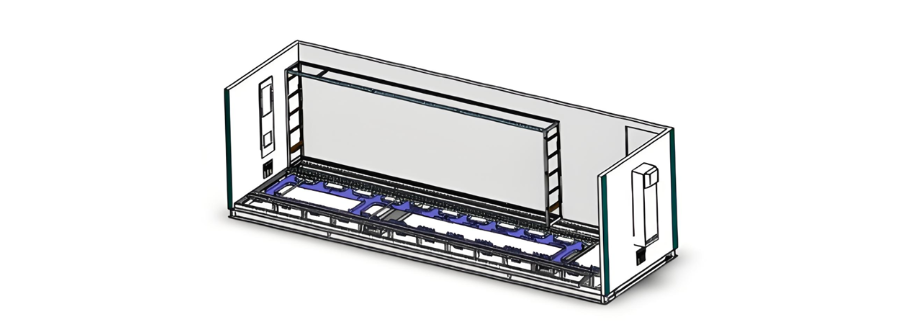
Figure 1 Schematic diagram of the installation components for the rack-mounted structure foundation
These basic installation components are manufactured by CNC machines through sheet metal processing, enabling precise control of dimensions and providing a solid foundation for the installation of rack units. Given the relatively large size of the basic installation components, the installation of the frame inside the cabin is carried out simultaneously with the manufacturing of the prefabricated cabin body.
1.2 The Second Layer of the Nested Installation Structure
As the middle layer for rack installation, this installation component can be shared by the core functional modules on both the left and right sides. It also serves the purpose of fire isolation for equipment.
1.3 The Third Layer of the Nested Installation Structure
On the rack bearing unit, single - bay protection devices, measurement and control devices, switches, terminal blocks, buttons, etc. are installed. These components are wired and debugged as an independent module, forming a self - contained rack functional unit, as illustrated in Figure 2.

Figure 2 Schematic diagram of the rack functional unit
The production, installation, and debugging of the rack are parallel processes to the production and installation of the cabin itself, without affecting each other's construction schedules. This completely transforms the previous production mode where switchboard - type structures required in - cabin wiring, significantly enhancing the efficiency of wiring in prefabricated cabins.
After all equipment is installed, various devices within the rack are connected through the upper and lower wire troughs that run horizontally through the rack, enabling seamless interconnection of the in - cabin equipment. Moreover, the wire troughs inside the rack form a grid - like structure, allowing various devices between racks to be connected via this grid - shaped wiring system.
Once all the wiring and debugging of the equipment within the rack are completed, the top cover, side cover plates, and front cover plates of the rack are installed, as depicted in Figure 3.
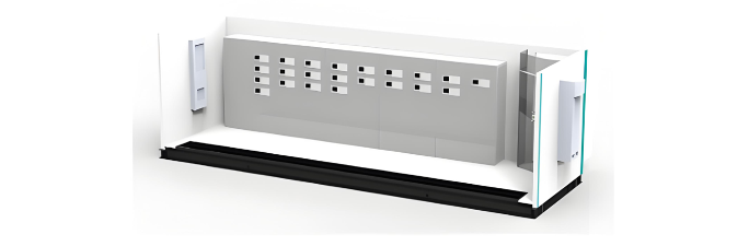
Figure 3 Effect drawing of the completed rack installation
The equipment within the rack of the prefabricated cabin is arranged in an offset manner. This article takes a 220 kV line protection and measurement and control unit as an example to illustrate the layout of the 220 kV rack equipment framework.
2. Design of the Standardized Scheme for Equipment Arrangement within the Rack of the Prefabricated Cabin
As shown in Figure 4, according to the configuration requirements of a 220 kV substation in the equipment installation area, for a single bay, it is necessary to configure two protection devices, one measurement and control device, two buttons, and several terminal blocks. Vertical wire troughs are installed in the wiring area, and locking buckles are configured to prevent accidental operations.
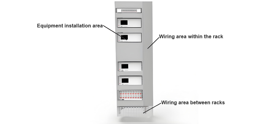
Figure 4 Schematic diagram of the device layout
3. Design of Cable Laying Scheme
3.1 Separate Routing of Optical and Electrical Cables
The dimensions of the rack remain 2260 (height) × 700 (width) × 600 (depth) mm. A wire trough with a height of approximately 40 mm is installed beneath each layer of equipment. Optical and electrical cables are routed separately, and all cables are laid out in a classified and zoned manner. As depicted in Figures 5 and 6, fiber optic jumpers are arranged on the left - hand side of the channel, while electrical cables are positioned on the right. Cables on the same side are bundled and placed together according to the installation positions of the devices.
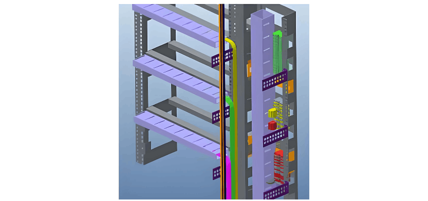
Figure 5 Schematic diagram of optical cable split-fiber layout
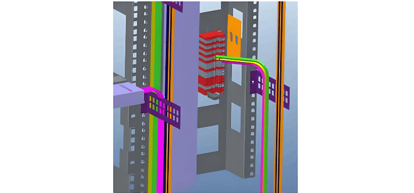
Figure 6 Schematic diagram of cable layout
3.2 Installation of a Centralized Transfer Rack
A centralized transfer rack for prefabricated optical cables, 700 mm wide, is installed inside the cabin. It is used to facilitate the connection between prefabricated optical cables and patch cables. The rack adopts a 40U installation framework, with the transfer boxes installed inside the framework, leaving sufficient space for the layout of front - end prefabricated optical cables and patch cables. Outdoor optical cables are converted into patch cables through the transfer cabinet. These patch cables are then transformed into fiber optic jumpers via the optical distribution frames within each cabinet and connected to various devices, thus completing the optical cable connection process. An inlet/outlet for the cable channel, which is connected to the station's cable trench, is provided inside the cabin.
4. Conclusions
The prefabricated cabin adopts a hierarchical nested rack structure. The framework is composed of several rack units, enabling the nested cabinets and the cabin body to be manufactured simultaneously and independently, which significantly improves construction efficiency.
The devices within the rack are functionally zoned, standardizing the arrangement of equipment inside the cabin.
Optical and electrical cables inside the prefabricated cabin adopt a bottom - routing method. The bottom of the cabin is arranged in layers, and wire trough boxes are installed beneath the switchboards, achieving the separation of optical and electrical cables.


