Research on Low - Voltage Anti - DC Current Transformer and Detection Device

Dyson
07/16/2025
Topics
Focused on the design of electrical equipment, proficient in electrical principles and relevant specifications, and skilled in using design software. From intelligent substations to various types of electrical equipment, I am adept at optimizing design solutions, integrating new technologies. With practical experience and collaborative management capabilities, I deliver outstanding electrical design achievements.
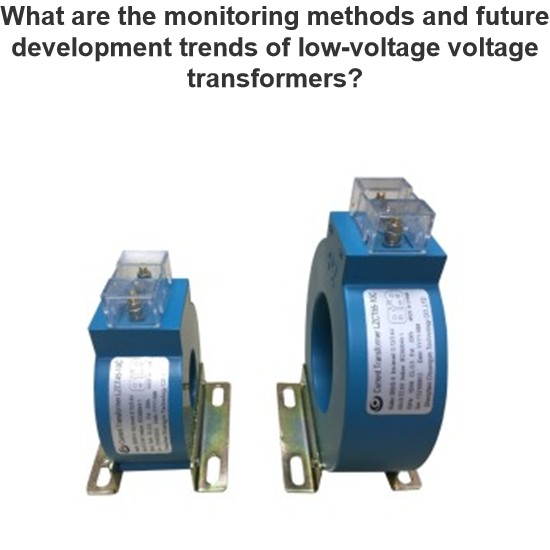
What are the monitoring methods and future development trends of low-voltage voltage transformers?
With the continuous advancement of smart grid technology, intelligent monitoring systems are playing an increasingly important role in preventing and addressing faults in voltage transformers. These modern intelligent monitoring systems can collect key parameters from voltage transformers in real time—such as partial discharge levels, temperature, and oil quality—and use data analysis algorithms to assess the health status of the equipment, enabling early fault warnings and precise l
Echo
07/16/2025
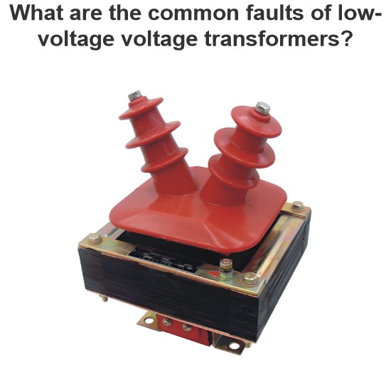
What are the common faults of low-voltage voltage transformers?
1. Open - Circuit Fault on the Secondary SideOpen - circuit in the secondary side is a typical fault of low - voltage voltage transformers, showing abnormal voltmeter readings (zero/fluctuation), faulty power meters, buzzing noises, and core overheating. When open - circuited, the secondary voltage spikes (no secondary current to balance the primary EMF), causing core saturation, flux distortion, and potential overheating/damage.Causes include loose terminals, poor contact, or human error. In lo
Oliver Watts
07/16/2025
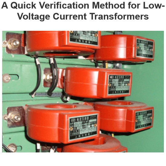
A Quick Verification Method for Low-Voltage Current Transformers
1. Selection of Low - Voltage Current Transformer ConfigurationThere are many factors leading to wrong selection of low - voltage current transformers in civil construction projects. For example, common factors include design problems: the calculated coefficient designed for the load of electrical equipment is relatively large, or the transformation ratio of the current transformer is selected incorrectly. Such a series of reasons will affect the use of electrical equipment. Therefore, in the co
James
07/16/2025

A Quick Verification Method for Low-Voltage Current Transformers
To ensure safe operation of the power system, power equipment operation must be monitored/measured. General devices can’t connect to primary high - voltage equipment directly; instead, large primary currents are scaled down for current transformation, electrical isolation, and use by measurement/protection devices. For AC large - current measurement, conversion to a unified current eases secondary instrument use.Current transformers split into measurement - and protection - type, with accu
Oliver Watts
07/16/2025


