A Quick Verification Method for Low-Voltage Current Transformers

James
07/16/2025
Professionalism builds strength. As an expert in the installation and operation of electrical equipment, I am proficient in the installation process and strictly adhere to standards. I skillfully master the operation essentials and can swiftly eliminate faults. With a heart that constantly explores new knowledge, I illuminate the path to the efficient operation of electrical equipment.
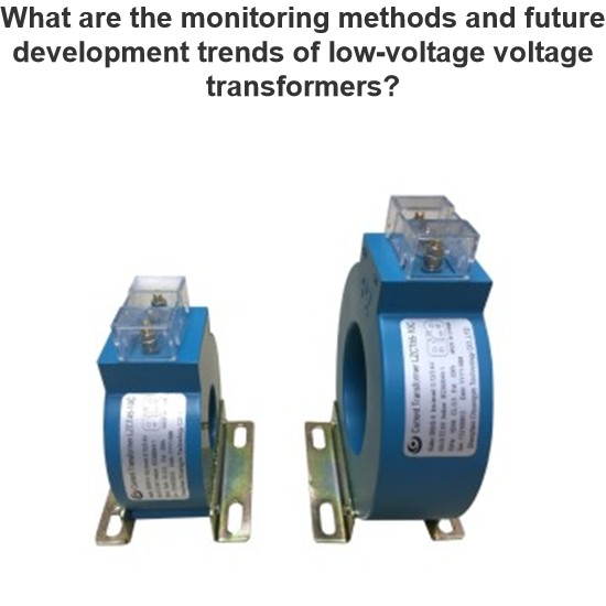
What are the monitoring methods and future development trends of low-voltage voltage transformers?
With the continuous advancement of smart grid technology, intelligent monitoring systems are playing an increasingly important role in preventing and addressing faults in voltage transformers. These modern intelligent monitoring systems can collect key parameters from voltage transformers in real time—such as partial discharge levels, temperature, and oil quality—and use data analysis algorithms to assess the health status of the equipment, enabling early fault warnings and precise l
Echo
07/16/2025
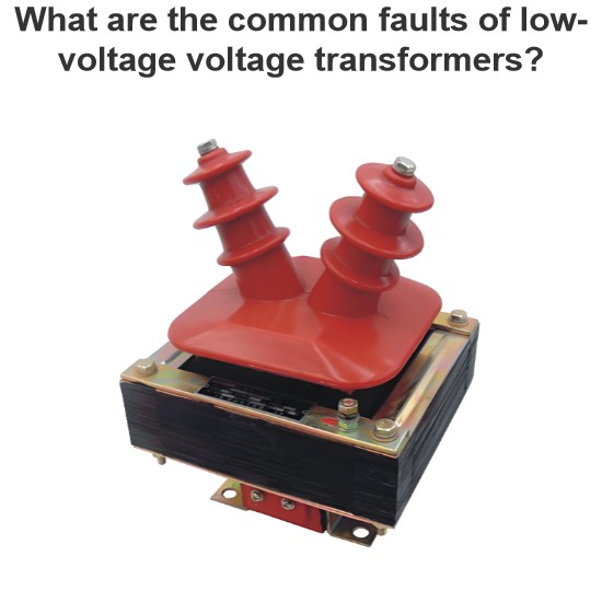
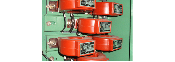
What are the common faults of low-voltage voltage transformers?
1. Open - Circuit Fault on the Secondary SideOpen - circuit in the secondary side is a typical fault of low - voltage voltage transformers, showing abnormal voltmeter readings (zero/fluctuation), faulty power meters, buzzing noises, and core overheating. When open - circuited, the secondary voltage spikes (no secondary current to balance the primary EMF), causing core saturation, flux distortion, and potential overheating/damage.Causes include loose terminals, poor contact, or human error. In lo
Oliver Watts
07/16/2025
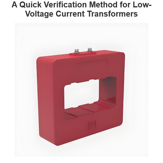
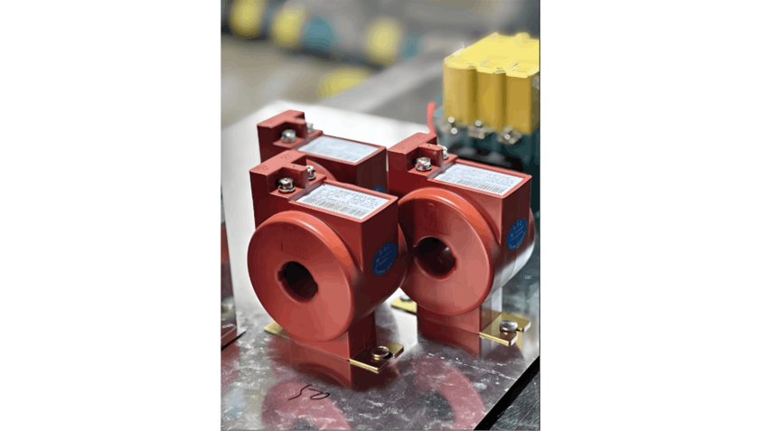
A Quick Verification Method for Low-Voltage Current Transformers
To ensure safe operation of the power system, power equipment operation must be monitored/measured. General devices can’t connect to primary high - voltage equipment directly; instead, large primary currents are scaled down for current transformation, electrical isolation, and use by measurement/protection devices. For AC large - current measurement, conversion to a unified current eases secondary instrument use.Current transformers split into measurement - and protection - type, with accu
Oliver Watts
07/16/2025
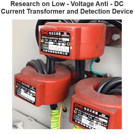
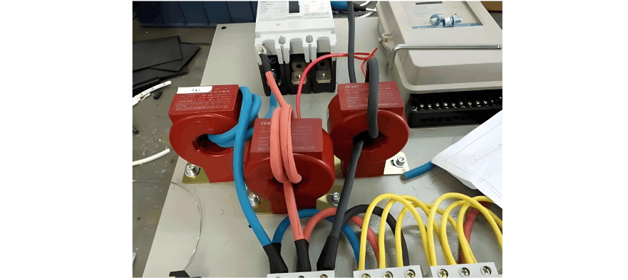
Research on Low - Voltage Anti - DC Current Transformer and Detection Device
1. Overview of Components and IssuesTA (low-voltage current transformer) and electric energy meters are key components of low-voltage electric energy metering. The load current of such meters is no less than 60A. Electric energy meters vary in type, model, and anti-DC performance, and are connected in series in the metering device. Due to the lack of anti-DC capability, they suffer from metering errors under DC component loads, usually caused by non-linear loads. With the increasing use of DC or
Dyson
07/16/2025


