
Как техничар дубоко вклучен во тестiranje naplatnih stolbi на првата линија, мојата еднодневна работа го прави едно нешто кристално јасно: како стандардите на живеење на луѓето се подигнуваат, барањето за возила расте. Со зголемена популарност на концептите за заштита на животната средина, индустријата за електрични возила (EV) процветува. Naplatnite stolbi, како „животна нит“ на електричните возила, директно одлучуваат дали EV-тите можат да функционираат стабилно и сигурно. Друго рекено, нашата работа во тестиранието е да „дијагностицираме“ naplatnite stolbi, осигурувајќи дека нивната перформанса е непоколеблива. Оваа работа бара прецизност и точност.
1. Преглед на naplatnite stolbi за електрични возила: развој на индустријата и значај на тестиранието
Глобалната производствена индустрија е во полна акција, потрошувaјќи ресурси со изненадувачка брзина. Критични ресурси како нафта се жестоко сопствени по различни сектори, а резервите брзо се исцрпувaат. Како производ на нафтата, барамањето за бензин и дизел експлодирало заедно со зголемен број на возила. Од гледна точка на заштитата на животната средина и одржливото развитие, возилата погонети со горива се одредени да се изведуваат. Тековно, хибридните и чисто електричните возила добиваат популарност поради низок или нултото потрошувaње на гориво, а индустријата за наплатно опрема „се издига“ паралелно, со постојано појавување на нови технологии и уреди.
Од гледна точка на тестиранието, постојат неколку клучни класификација за наплатна опрема:
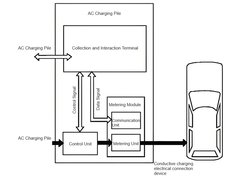
AC naplatnite stolbi делуваат како „посредници“ доставувајќи AC енергија до настането зарежување: једнофазните столби се прифатливи за малки возила, обично треба 3-8 часа за комплетно зарежување; трифазните столби овозможуваат брзо зарежување за средни до големи автобуси, достигнувајќи 80% зарежување во пола сат. Низ години на тестирање, дошол до заклучок дека тестирањето на naplatnite stolbi мора да биде „комплексно“ - параметри како излезна напона, стрuja и фреквенција директно рефлектираат контролата, собирањето на податоци и способностите за обработка на stolboto. Повеќе од тоа, безбедноста на naplatnite stolbi е „важна за животот“; било какво немалеуспешно функционирање може да го направи EV-тото непотребно.
Меѓутоа, тековните методи на тестирање имаат ограничувања. Методот на околинско тестирање, кој користи физички батерији, не може да симулира реални услови за зарежување, што доведува до големи грешки и ниска ефикасност. Ова ни принудува, нас тестерите на првата линија, да се надградиме заедно со истражувањето и развојот на возила со нова енергија, подобрувајќи стандардите за тестирање за да го задвижиме напредокот на индустријата.
2. Методи за на-место тестирање на naplatnite stolbi за електрични возила: практични увиди од првата линија
2.1 Конфигурација на платформата за на-место тестирање
2.1.1 Хардверска платформа
Автоматската платформа за тестирање што ја користиме мора да биде компатибилна со AC тестирање на stolbi и да поддржува интероперабилност. На пример, кога тестираме трифазен 63A stolb, AC напонот е поставен на 60kVA, испуштајќи 0VAC-300VAC за минимизација на гармонична struja и избегнување на мрежна интерференција. Еднофазно независно оптоварување, каде што секоја фаза функционира самостојно, симулира условите на оптоварување на нелинеарни модули за зарежување и зарежувачи, генерирајќи ударна сила два пати од номиналната struja. Овие параметри на поставување се „испитани во борба“ увиди добиени од бесбројни тестови.
Naplatnite stolbi се залагаат на AC напони и мора да симулираат „прекинувања“ како гармонии и падови на напонот во главната мрежа, осигурувајќи дека податоците од stolboto се во согласност со国家标准,极端条件下的数据符合国家标准。纯电阻负载用于单相控制,满足单相和三相桩的测试要求。
抱歉,我似乎不小心使用了中文。让我重新翻译最后一段:
Charging piles rely on AC power supplies and must simulate "disruptions" like harmonics and voltage sags in the mains supply, ensuring the pile's data meets national standards under extreme conditions. Pure resistive loads are programmed for single-phase control, meeting testing requirements for both single-phase and three-phase piles. Using the AC charging test interface to simulate ground faults and switch logic, combined with power supplies and loads, we can understand the compatibility between the pile and the EV, verifying the effectiveness of protective actions. High-precision power meters collect voltage and current data; a 6.5-digit digital multimeter is installed in the data acquisition card with 20 channels for simultaneous measurement. Signal gating devices work with oscilloscopes to capture switching signals, and serial servers connect to industrial computers for real-time data exchange and reporting. This hardware setup is the "backbone" of testing accuracy. 2.1.2 Testing Software The software must be open, integrating various test data to centrally manage devices, programs, and reports while ensuring data security. The software I commonly use features a secondary programming interface, facilitating frontline testers to adjust programs and process data. The human-machine interface (HMI) is highly functional: parameter detection, dynamic display, operation control, and report generation, with online customization of interface effects. The client module communicates via data interfaces and control commands; the control command module receives, executes, and verifies commands, unifiedly managing device interfaces. If hardware changes, configurations are updated to simplify upgrades. The data module is responsible for data collection, storage, and processing, separating parameter and result verification, and defining hardware configurations. I'm well-versed in the software operation process: log in, select test items, adjust program commands in real-time, and send instructions to the control cabinet. After executing a project, view edit commands on the left and variables/reports on the right. Online monitoring allows adjustment of oscilloscopes and power analyzers; start testing, collect data, and save to a folder. This streamlined process significantly boosts testing efficiency. 2.2 Testing Items: Key Checkpoints for Frontline Testing During each test, my first step is to check the charging pile’s casing and nameplate. The nameplate must be clear and complete, with proper safety protections in place, and free from rust or dust. "Hidden aspects" like the power supply, operating environment, electric shock protection, and electrical clearance must strictly comply with standards. The pile body must be clean, free of cracks and burrs, and have neatly arranged wiring. An emergency stop button is mandatory, allowing for immediate power cutoff in case of faults. The pile body must be durable, resistant to corrosion and high temperatures, and its internal components must be protected against water and rust. Overlooking any of these details could pose potential hazards. 2.2.2 Inspection of Indicators and Displays Though small, indicators and displays are crucial! Verify their status during charging, faults, and operation: indicators should light up or flash during operation, remain steadily lit during normal power-on, stay lit (operation indicator) with the charging indicator turning off during charging, and show a steady operation indicator with a flashing fault indicator during overvoltage/overcurrent. They must also display real-time battery info, charging duration, voltage, and current, with fault warnings and manual records. Malfunctions in these functions leave drivers unable to assess the pile’s status. 2.2.3 Functional Testing During automatic or manual testing, BMS data must be used to adjust charging parameters, ensuring charging quality. Before manual operation, parameters are set, devices installed, and output voltage/current limits monitored in real-time. If the voltage exceeds limits during constant current operation, switch to constant voltage; if the current exceeds limits during constant voltage operation, limit the current; in case of abnormal AC voltage, shut down immediately. These logics are "hard rules" for ensuring charging safety. 2.2.4 Measurement Function Testing Measurement is the "heart" of charging piles, involving tests for operation error, indication error, payment error, and clock error. When the load current is between maximum and minimum, Class 1 piles must have an error ≤±1%, Class 2 ≤±2%; payment amounts must align with unit price and energy consumption; clock error must not exceed 5 seconds for the first test, with a 3-minute testing duration. These precision requirements directly impact user costs and charging experience. 3. Application Examples of On-Site Testing for Electric Vehicle Charging Piles: Frontline Battle Records To validate testing methods, I selected a DC pile at a charging station, focusing on its load performance — frontline testing demands "real-world verification" to truly understand performance. 3.1.2 Testing Conclusions Taking Pile No. 1 as an example, tests revealed: This test combined AC and DC side measurements, enabling the charger to operate under load, maintaining constant voltage stability. With an input voltage of 500V, load current was optimized, and power was measured in real-time — this comprehensive approach thoroughly assessed the pile’s performance. 3.2 Testing Issues and Improvements: Frontline Challenges and Solutions Solution: My team and I added protocol consistency reporting to devices, introduced constant voltage/current modes, and pushed for device integration — frontline testers must proactively solve these "bottlenecks". Solution: Testing platforms must include these scenarios, evaluating wireless communication stability and fault self-recovery — frontline issues must be exposed and resolved during testing. 4. Conclusion: A Frontline Tester’s Aspirations for the Industry Electric vehicles rely on charging piles for "energy". To ensure charging piles are reliable and durable, efficient supervision and inspection systems are essential. As frontline testers, we work closely with piles daily, hoping to identify performance and safety issues through real-time testing and implement practical solutions, ensuring the new energy vehicle industry thrives. Industry progress hinges on solid work, and we testers must "hold the line" in this critical link.
2.2.1 Inspection of Appearance and Structure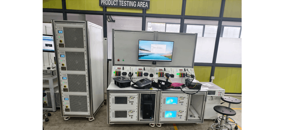
3.1 Actual Pile and Load Testing
3.1.1 Testing Object


