• Product
  • Suppliers
  • Manufacturers
  • Solutions
  • Free tools
  • Knowledges
  • Experts
  • Communities
Search


Impact Analysis of Voltage Transformer Installation on Line Side vs. Load Side of Power Inlet Circuit Breaker for (ATS)

James
Field: Electrical Operations
China
Automatic backup switching (ABTS) devices are core components ensuring the safe, reliable, and stable operation of factory power grids. Their startup logic strictly follows the dual criteria of "loss of voltage in the working power supply + no - current detection", effectively avoiding misjudgments caused by secondary disconnection of voltage transformers (VTs) or maloperations of ABTS due to secondary circuit faults of current transformers (CTs). The activation condition requires both "no voltage and no current" or "voltage/current values below the protection setting", with no exceptions.
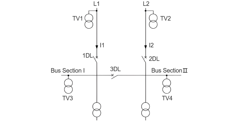
ABTS relies on VTs to collect voltage signals and CTs to collect current signals. Thus, the installation positions of these transformers directly determine the accuracy of the device in judging the status of the working power supply. Among them, regardless of whether CTs are installed on the upper or lower side of the power inlet circuit breaker, ABTS can accurately identify "circuit breaker current - carrying status and busbar load - carrying conditions"; however, there are significant differences in how ABTS judges the live status of busbars when VTs are installed on the upper side (inlet side) versus the lower side (busbar side) of the circuit breaker, which requires focused analysis. The system wiring is shown in Figure 1.
1. Voltage Transformer Installed on the Upper Side of the Power Inlet Circuit Breaker (Inlet VT)
(1) Normal Operation of the Inlet Power Supply
When ABTS takes power from the line voltage transformer TV1, if circuit breaker 1DL is in the "working position + closed state", TV1 collects the inlet voltage, which is equivalent to the busbar voltage. ABTS then determines that Section I busbar is live.
(2) Loss of Inlet Power Supply
When the inlet power supply fails, TV1 collects a voltage of zero and the CT collects a current of zero, triggering ABTS to act: first trip 1DL, then close bus - tie circuit breaker 3DL, restoring power to Section I busbar and allowing the load to continue operating.
(3) Maloperation of the Circuit Breaker (Core Hidden Risk Scenario)
If 1DL switches from the closed to the open position due to misoperation or mechanical failure, Section I busbar loses power and the load shuts down. The CT collects a current of zero, but TV1 still collects the normal inlet - side voltage (not dropping to the protection setting), so ABTS fails to detect "busbar voltage loss" and cannot start. 3DL cannot close, causing prolonged power loss on Section I busbar and severe production interruptions.
(4) Logic Optimization Solution
Precise identification requires implementing a "circuit breaker position interlock + voltage criterion": TV1 - collected voltage is equivalent to the busbar voltage only when 1DL is in the "working position + closed state"; if the circuit breaker position is abnormal (non - working position/open state), ABTS forcibly judges the busbar voltage as 0. Additionally, a "circuit breaker position verification" logic must be added: after detecting busbar voltage loss, ABTS verifies the status of 1DL before deciding to "trip 1DL + close 3DL" or directly "close 3DL".
2. Voltage Transformer Installed on the Lower Side of the Power Inlet Circuit Breaker (Busbar VT)
When ABTS takes power from the busbar voltage transformer TV3, if circuit breaker 1DL is in the "working position + closed state", TV3 directly collects the voltage of Section I busbar, and ABTS obtains the actual busbar voltage signal.
(1) Loss of Inlet Power Supply
When the inlet power supply fails or 1DL maloperates to the open position, TV3 collects a voltage of zero and the CT collects a current of zero, triggering ABTS to act:
  • If the inlet power supply fails: trip 1DL → close 3DL to restore busbar power;
  • If the circuit breaker maloperates: directly close 3DL to restore busbar power, with no load interruption.
(2) Advantage Analysis
The busbar VT can "realtime and directly reflect the busbar live status" without relying on circuit breaker position criteria. ABTS has a simpler action logic, accurately identifying busbar voltage loss scenarios and avoiding misoperation/non - operation risks.
3. Comparative Analysis of the Two Installation Schemes
(1) Complexity of Action Logic
  • Inlet - side installation (TV1): Requires adding "circuit breaker position verification + voltage conversion logic", increasing the difficulty of ABTS action judgment;
  • Busbar - side installation (TV3): Directly collects busbar voltage with clear logic and high action reliability.
(2) Potential Risks (Major Hidden Danger of Inlet - Side Installation)
If TV1 on the inlet side is paralleled with line L1, when L1 loses power, ABTS triggers the "trip 1DL → close 3DL" action. The busbar voltage is then reverse - fed to L1 through TV1, causing a "voltage reverse charging accident": at best, tripping the air circuit breaker on the L1 side and causing secondary voltage loss; at worst, damaging equipment and even triggering personal electric shock risks.
4. Conclusion and Recommendations
To ensure ABTS "acts accurately and reliably" during busbar voltage loss and avoid voltage reverse charging accidents when VTs are paralleled, VTs should be installed on the lower side (busbar side) of the power inlet circuit breaker to directly collect busbar voltage via the busbar VT. This enables realtime reflection of the actual busbar status, providing reliable criteria for ABTS. It ensures the device acts quickly and accurately during busbar voltage loss, minimizing impacts on production and daily life.
Give a tip and encourage the author!
Recommended
Technical Analysis of 220 kV High-Voltage Cable Construction in Winter
1.Work Environment Requirements and Safeguard MeasuresBased on technical requirements for cable equipment storage, laying, transportation, laying, transposition, testing, and cable terminations, the project owner and construction units have conducted extensive trials and implemented protective measures regarding ambient temperature, humidity, bending radius, traction control, and route optimization. These measures ensure high-voltage cable quality and on-site safety under harsh winter conditions
James
09/03/2025
Considerations and Recommendations for Flame-Retardant Selection of High-Voltage Cables
1.Flame-Retardant Cable Classification StandardsThe flame-retardant standard system is divided into two main categories. The first category follows the "Classification of Burning Behavior for Electric and Optical Fiber Cables" GB 31247. Cables complying with this standard system are widely used in densely populated areas such as high-speed railways and subways. This standard imposes strict requirements on parameters such as smoke density, heat release, and total smoke production, and cables typi
James
09/03/2025
Must DC circuit breakers always be bipolar?
For a 24V switch-mode power supply branch, I used a single-pole DC circuit breaker, with the negative pole subjected to equipotential bonding (previously, I even directly used AC breakers as substitutes—the main difference being arc-extinguishing performance, but how significant can the arc be in a few-amp low-current short circuit?).During a design review, an expert stated that DC circuit breakers must be bipolar, arguing that DC has positive and negative poles, unlike AC!I'm puzzled—where is t
James
09/02/2025
What Should Be Noted During the Installation Process of Indoor Load Switches?
The installation quality of indoor load switches directly affects their operational safety and service life. It must be carried out focusing on four core principles: "safety protection, standardized wiring, mechanical compatibility, and insulation assurance." Specific precautions are as follows:1.Basic Preparation and Safety Protection Before Installation: Verify that the switch model and specifications (e.g., rated voltage, current) match the actual power distribution requirements to avoid "usi
James
08/27/2025
Seed Inquiry
Download
Get the IEE Business Application
Use the IEE-Business app to find equipment, obtain solutions, connect with experts, and participate in industry collaboration anytime, anywhere—fully supporting the development of your power projects and business.