Maxwell Inductance Capacitance Bridge: Diagram & Applications


What is Maxwell Bridge
A Maxwell Inductance Capacitance Bridge (known as a Maxwell Bridge) is a modified version of a Wheatstone bridge which is used to measure the self-inductance of a circuit. A Maxwell bridge uses the null deflection method (also known as the “bridge method”) to calculate an unknown inductance in a circuit. When the calibrated components are a parallel capacitor and resistor, the bridge is known as a Maxwell-Wien bridge.
The working principle is that the positive phase angle of an inductive impedance can be compensated by the negative phase angle of a capacitive impedance when put in the opposite arm and the circuit is at resonance (i.e., no potential difference across the detector and hence no current flowing through it). The unknown inductance then becomes known in terms of this capacitance.

There are two types of Maxwell bridges: Maxwell’s inductor bridge, and Maxwell’s inductor capacitance bridge. In Maxwell’s inductor bridge, only inductors and resistors are used. In Maxwell’s inductor capacitance bridge, a capacitor is also added to the circuit.
As both types of these Maxwell bridge is based on an AC bridge, we’ll first explain the working principle of an AC bridge before explaining a Maxwell bridge.
AC Bridges
An AC Bridge consists of a source, a balance detector and four arms. In AC bridges, all four arms contain an impedance. The AC bridges are formed by replacing the DC battery with an AC source and galvanometer by detector of Wheatstone bridge.
They are highly useful to find out inductance, capacitance, storage factor, dissipation factor etc.
Now let us derive the general expression for an AC bridge balance. The figure below shows an AC bridge network:
Here Z1, Z2, Z3 and Z4 are the arms of the bridge.
Now at the balance condition, the potential difference between b and d must be zero. From this, when the voltage drop from a to d equals to drop from a to b both in magnitude and phase.
Thus, we have from figure e1 = e2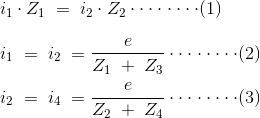
From equation 1, 2 and 3 we have Z1.Z4 = Z2.Z3 and when impedance are replaced by admittance, we have Y1.Y4 = Y2.Y3.
Now consider the basic form of an AC bridge. Suppose we have bridge circuit as shown below, In this circuit R3 and R4 are pure electrical resistances. Putting the value of Z1, Z2, Z3 and Z4 in the equation that we have derived above for AC bridge.
Now equating the real and imaginary parts, we get:
Following are the important conclusions that can be drawn from the above equations:
We get two balanced equations that are obtained by equating real and imaginary parts this means that for an ac bridge both the relation (i.e.magnitude and phase) must be satisfied at the same time. Both the equations are said to be independent if and only if both equations contain a single variable element. This variable can be inductor or resistor.
The above equations are independent of frequency that means we do not require exact frequency of the source voltage and also the applied source voltage waveform need not to be perfectly sinusoidal.
Maxwell’s Bridge
There are two main types of Maxwell Bridges:
Maxwell’s inductor bridge
Maxwell’s inductor capacitance bridge
Maxwell’s Inductance Bridge
Let us now discuss Maxwell’s inductance bridge. The figure shows the circuit diagram of Maxwell’s inductor bridge.
In this bridge, the arms bc and cd are purely resistive while the phase balance depends on the arms ab and ad.
Here l1 = unknown inductor of r1.
l2 = variable inductor of resistance R2.
r2 = variable electrical resistance.
As we have discussed in AC bridge according to balance condition, we have at balance point: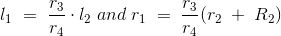
We can vary R3 and R4 from 10 ohms to 10,000 ohms with the help of resistance box.
Maxwell’s Inductance Capacitance Bridge
In this Maxwell Bridge, the unknown inductor is measured by the standard variable capacitor.
Circuit of this bridge is given below,
Here, l1 is unknown inductance, C4 is a standard capacitor.
Now under balance conditions, we have from AC bridge that Z1.Z4 = Z2.Z3
Let us separate the real and imaginary parts, then we have,
Now the quality factor is given by,
Advantages of Maxwell’s Bridge
The advantages of a Maxwell Bridge are:
The frequency does not appear in the final expression of both equations, hence it is independent of frequency.
Maxwell’s inductor capacitance bridge is very useful for the wide range of measurement of inductor at audio frequencies.
Disadvantages of Maxwell’s Bridge
The disadvantages of a Maxwell Bridge are:
The variable standard capacitor is very expensive.
The bridge is limited to measurement of low quality coils (1 < Q < 10) and it is also unsuitable for low value of Q (i.e. Q < 1) from this we conclude that a Maxwell bridge is used suitable only for medium Q coils.
The above all limitations are overcome by the modified bridge which is known as Hay’s bridge which does not use an electrical resistance in parallel with the capacitor.
Statement: Respect the original, good articles worth sharing, if there is infringement please contact delete.


