
| Brand | Wone Store |
| Model NO. | Planar Four-Axis Robot |
| Rated Load Capacity | 5kg |
| degree of freedom | 4-direction |
| Maximum working stroke | 700mm |
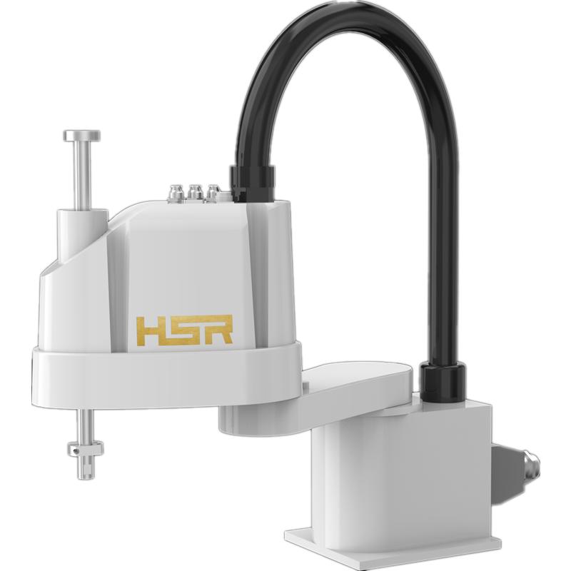
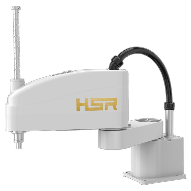
| Series | SR |
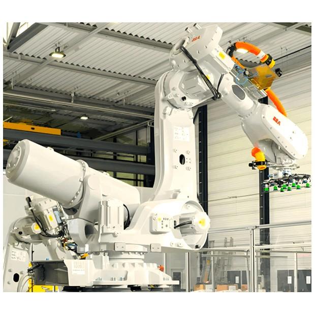
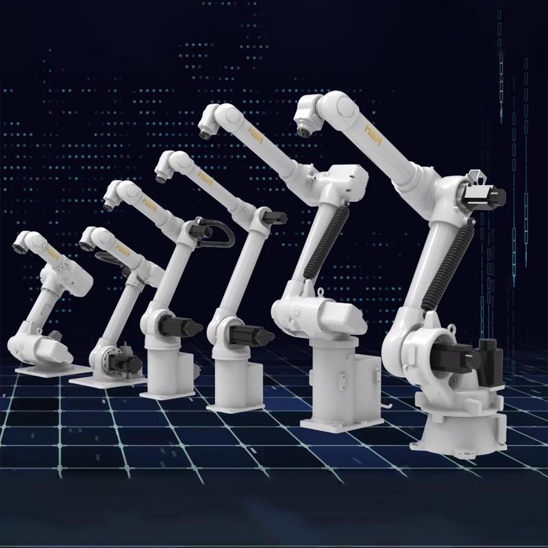
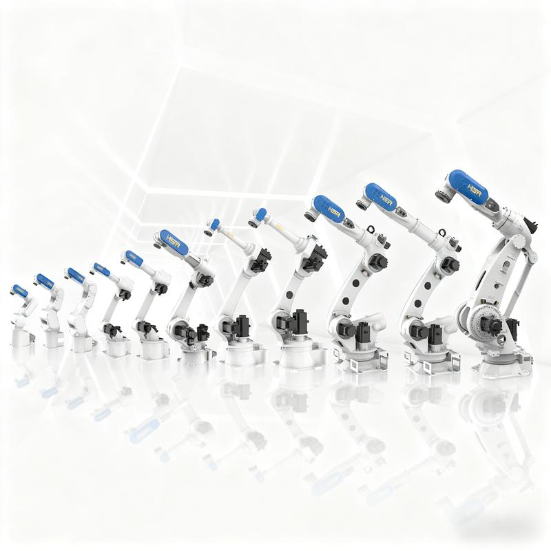
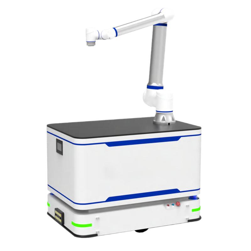
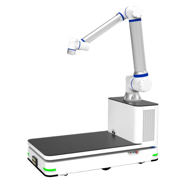
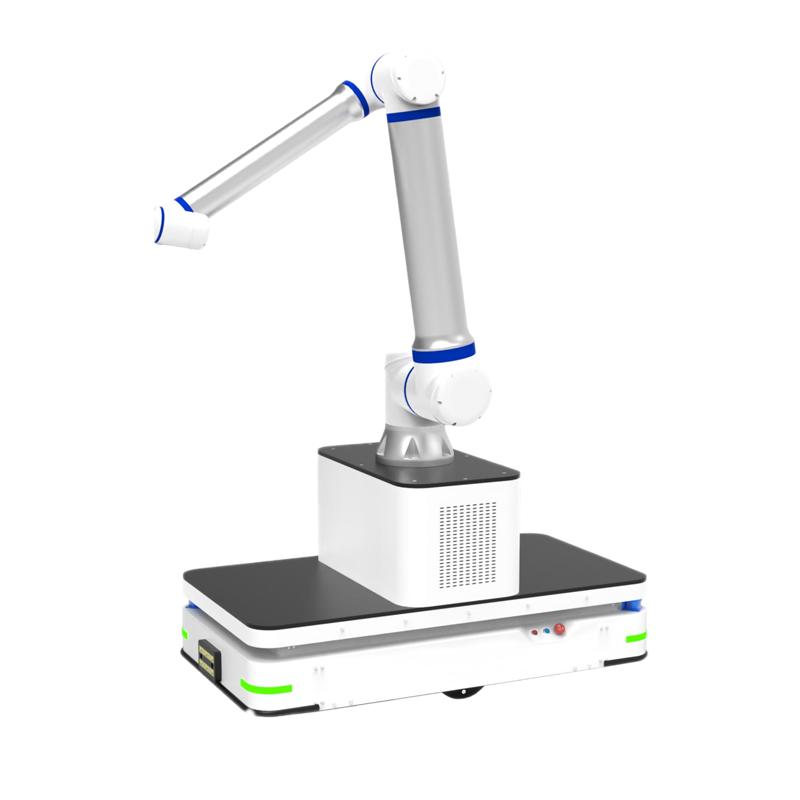
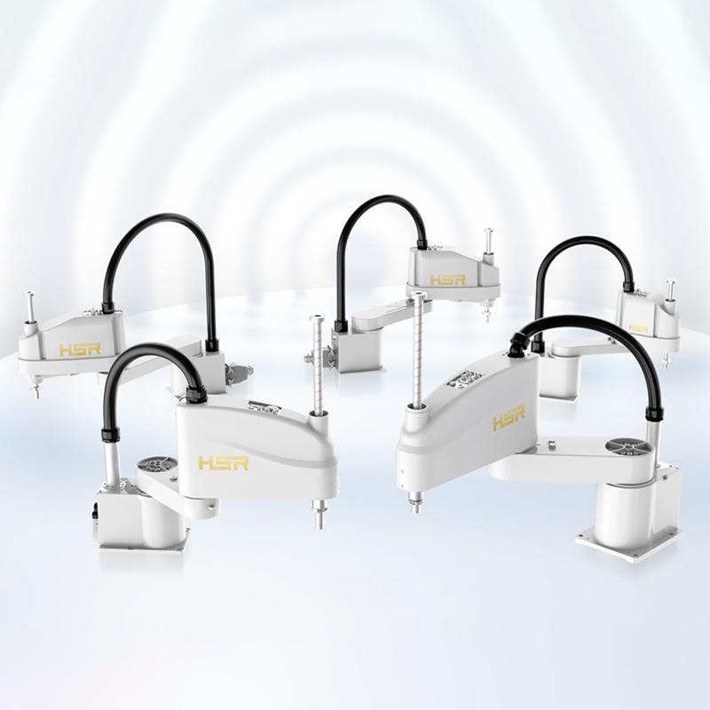
SR series robots are specially developed for desktop pick-up and installation applications with a load capacity of 1-20kg, which can be widely used in electronic products industry, pharmaceutical industry and food industry.
Key features
High speed, high precision
Lightweight structure design with high power density motor application, repeated positioning accuracy of ±0.01mm.
High ease of use, high security
Equipped with independent intellectual property control system, easy to operate, fast programming, support collision detection and other safety functions to ensure the safety of personnel and products.
High cost performance, well tested by the market
Cost-effective, long-tested market after many years of market inspection and a large number of applications, stable performance, high reliability, widely used in 3C electronics, packaging and printing, electronic information kitchen and other industries.
High load, high inertia
Using self-developed control technology, it supports 10/20kg load under high torque conditions, and the 4-axis inertia of the planetary reducer is larger and the speed performance is better.
High rigidity, high reliability
The whole system adopts RV reducer to ensure the rigidity of the joint, while adjusting the inertia ratio to improve the dynamic response and service life of the robot.
High speed, high performance
It can withstand higher start-stop inertia, can meet higher speed operation under full load, and meet the requirements of different applications.
Technology Parameters
Industrial robots |
SR3-400 |
SR5-700 |
SR6-500 |
SR6-600 |
|
Degrees of freedom |
4 |
4 |
4 |
4 |
|
Maximum load |
1kg/3kg |
2kg/5kg |
2kg/6kg |
2kg/6kg |
|
Maximum working radius |
400mm |
700mm |
500mm |
600mm |
|
Repeat positioning accuracy |
±0.01 mm |
±0.02 mm |
±0.02 mm |
±0.02 mm |
|
Range of motion |
J1 |
±132° |
±132° |
±132° |
±132° |
J2 |
±135° |
±150° |
±150° |
±150° |
|
J3 |
0/-150mm |
0/-200mm |
0/-200mm |
0/-200mm |
|
J4 |
±360° |
±360° |
±360° |
±360° |
|
Maximum speed |
J1 |
530°/s, 9.24 rad/s |
335°/s, 5.84 rad/s |
375°/s, 6.54 rad/s |
375°/s, 6.54 rad/s |
J2 |
700°/s, 12.21 rad/s |
600°/s, 10.46 rad/s |
600°/s, 10.46 rad/s |
600°/s, 10.46 rad/s |
|
J3 |
1165mm/s |
1111mm/s |
1111mm/s |
1111mm/s |
|
J4 |
2600°/s, 43.35 rad/s |
2000°/s, 34.88 rad/s |
2000°/s, 34.88 rad/s |
2000°/s, 34.88 rad/s |
|
Allowing for the moment of inertia |
J4 |
0.005 kgm3 |
0.013 kgm3 |
0.013 kgm3 |
0.013 kgm3 |
Allowable Torque |
J4 |
3.29Nm |
4.23Nm |
4.23Nm |
4.23Nm |
Applicable Environment |
Temperature |
0°C to 45°C |
0°C to 45°C |
0°C to 45°C |
0°C to 45°C |
Humidity |
20% to 80% |
20% to 80% |
20% to 80% |
20% to 80% |
|
Other |
Avoid contact with flammable, explosive, or corrosive gases and liquids, and keep away from sources of electronic noise (such as plasma). |
||||
Teaching device cable length |
8m |
8m |
8m |
8m |
|
Body-to-cabinet connection cable length |
3m |
3m |
3m |
3m |
|
I/O parameters |
Digital inputs: 32-bit (NPN and PNP compatible), 32-bit digital outputs (NPN only) |
Digital inputs: 32-bit (NPN and PNP compatible), 32-bit outputs (NPN only) |
Digital inputs: 32-bit (NPN and PNP compatible), 32-bit digital outputs (NPN only) |
Digital inputs: 32-bit (NPN and PNP compatible), 32-bit outputs (NPN only) |
|
Body-prepared signal cable |
15-pin (aircraft connector) |
15-pin (aircraft connector) |
15 positions (airplane plug connection) |
15-pin (aircraft connector) |
|
Reserved air circuit |
3xφ6 |
3xφ6 |
3xφ6 |
3xφ6 |
|
Power capacity |
0.61kVA |
0.73kVA |
0.73kVA |
0.73kVA |
|
Rated power/voltage/current |
0.49 kW / Single-phase AC 220V / 2.7 A |
0.58 kW / Single-phase AC 220 V / 3.1 A |
0.58 kW / Single-phase AC 220 V / 3.1 A |
0.58 kW / Single-phase AC 220 V / 3.1 A |
|
Enclosure/Electrical Cabinet Protection Rating |
IP54/IP20 |
IP54/IP20 |
IP54/IP20 |
IP54/IP20 |
|
Installation method |
Floor and tabletop installation |
Floor and tabletop installation |
Floor and tabletop installation |
Floor and tabletop installation |
|
Body/Electrical Cabinet Weight |
17.5kg/10.65kg |
22.5kg/10.65kg |
19kg/10.65kg |
21.5kg/10.65kg |
|
Industrial robots |
SR10-600 |
SR10-800 |
SR20-800 |
SR20-1000 |
|
Degrees of freedom |
4 |
4 |
4 |
4 |
|
Maximum load |
5kg/10kg |
5kg/10kg |
10kg/20kg |
10kg/20kg |
|
Maximum working radius |
600mm |
800mm |
800mm |
1000mm |
|
Repeat positioning accuracy |
±0.025 mm |
±0.025 mm |
±0.025 mm |
±0.025 mm |
|
Range of motion |
J1 |
±135° |
±135° |
±132° |
±132° |
J2 |
±155° |
±155° |
±155° |
±155° |
|
J3 |
0/-300mm |
0/-300mm |
0/-400mm |
0/-400mm |
|
J4 |
±360° |
±360° |
±360° |
±360° |
|
Maximum speed |
J1 |
430°/s, 7.50 rad/s |
430°/s, 7.50 rad/s |
530°/s, 9.25 rad/s |
420°/s, 7.33 rad/s |
J2 |
650/s, 11.34 rad/s |
650°/s, 11.34 rad/s |
580°/s, 10.12 rad/s |
580°/s, 10.12 rad/s |
|
J3 |
2200mm/s |
2200mm/s |
2150mm/s |
2150mm/s |
|
J4 |
2250°/s, 39.26 rad/s |
2250°/s, 39.26 rad/s |
1700°/s, 29.67 rad/s |
1700°/s, 29.67 rad/s |
|
Allowing for the moment of inertia |
J4 |
0.02 kgm3 |
0.02 kgm3 |
0.082 kgm3 |
0.082 kgm3 |
Allowable Torque |
J4 |
8.83Nm |
8.83Nm |
21.86Nm |
21.86Nm |
Applicable Environment |
Temperature |
0°C to 45°C |
0°C to 45°C |
0°C to 45°C |
0°C to 45°C |
Humidity |
20% to 80% |
20% to 80% |
20% to 80% |
20% to 80% |
|
Other |
Avoid contact with flammable, explosive, or corrosive gases and liquids, and keep away from sources of electronic noise (such as plasma). |
||||
Teaching device cable length |
8m |
8m |
8m |
8m |
|
Body-to-cabinet connection cable length |
3m |
3m |
3m |
3m |
|
I/O parameters |
Digital inputs: 32-bit (NPN and PNP compatible), 32-bit digital outputs (NPN only) |
Digital inputs: 32-bit (NPN and PNP compatible), 32-bit digital outputs (NPN only) |
Digital inputs: 32-bit (NPN and PNP compatible), 32-bit digital outputs (NPN only) |
Digital inputs: 32-bit (NPN and PNP compatible), 32-bit outputs (NPN only) |
|
Body-prepared signal cable |
15-pin (aircraft connector) |
15-pin (aircraft connector) |
15-pin (airplane plug connection) |
15-pin (aircraft connector) |
|
Reserved air circuit |
3xφ6 |
3xφ6 |
2xφ6 + 1xφ8 |
2xφ6 + 1xφ8 |
|
Power capacity |
1.31kVA |
1.31kVA |
1.71kVA |
1.71kVA |
|
Rated power/voltage/current |
1.05 kW / Single-phase AC 220 V / 5.7 A |
1.05 kW / Single-phase AC 220 V / 5.7 A |
1.37 kW / Single-phase AC 220 V / 7.3 A |
1.37 kW / Single-phase AC 220 V / 7.3 A |
|
Enclosure/Electrical Cabinet Protection Rating |
IP54/IP20 |
IP54/IP20 |
IP54/IP20 |
IP54/IP20 |
|
Installation method |
Floor and tabletop installation |
Floor and tabletop installation |
Floor and tabletop installation |
Floor and tabletop installation |
|
Body/Electrical Cabinet Weight |
32kg/10.65kg |
35kg/10.65kg |
50kg/10.65kg |
53kg/10.65kg |
|