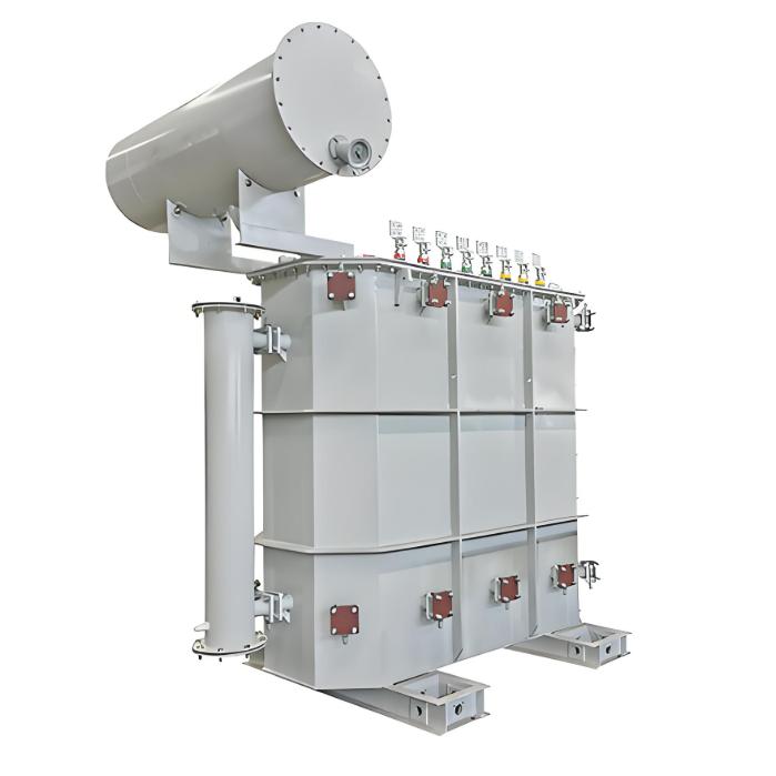
What is a Rectifier Transformer?
"Power conversion" is a general term encompassing rectification, inversion, and frequency conversion, with rectification being the most widely used among them. Rectifier equipment converts input AC power into DC output through rectification and filtering. A rectifier transformer serves as the power supply transformer for such rectifier equipment. In industrial applications, most DC power supplies are obtained by combining a rectifier transformer with rectifier equipment.
 What is a Power Transformer?
A power transformer generally refers to a transformer that supplies power to electric drive (motor-driven) systems. Most transformers in the power grid are power transformers.
Differences Between Rectifier Transformers and Power Transformers
1. Functional Differences
Functions of a Rectifier Transformer:
- To provide the rectifier system with an appropriate voltage;
- To reduce waveform distortion (harmonic pollution) caused by the rectifier system and minimize its impact on the grid.
Although a rectifier transformer still outputs AC power, it serves solely as the power source for rectifier equipment. Typically, its primary winding is connected in star (wye) configuration, while the secondary winding is connected in delta configuration. This arrangement helps suppress higher-order harmonics. The secondary delta connection has no grounded neutral point, so if a single ground fault occurs on the rectifier equipment, it will not cause equipment damage. Instead, a ground-fault detection device will issue an alarm signal. Additionally, electrostatic shielding is installed between the primary and secondary windings for enhanced isolation.
Rectifier transformers are primarily used in applications such as electrolysis, smelting, excitation systems, electric drives, cascade speed control, electrostatic precipitators, and high-frequency welding. Their structure differs slightly depending on the application. For example, rectifier transformers used in electrolysis are often designed with six-phase outputs to achieve smoother DC waveforms; when paired with a six-phase rectifier bridge externally, they produce a relatively ripple-free output.
For smelting and high-frequency welding, the transformer windings and structural components are optimized—based on the current waveform characteristics of thyristor rectifier circuits and harmonic suppression requirements—to reduce eddy current losses in windings and stray losses in metal parts. Nevertheless, their overall structure remains largely similar to standard transformers.
In contrast, power transformers are typically connected in Y/Y configuration with a grounded neutral point (to supply single-phase power). If used with rectifier equipment, a ground fault could cause severe damage to the rectifier system. Moreover, power transformers have poor capability to suppress the high-order harmonics generated by rectifier loads.
2. Difference in Applications
A transformer specifically designed to supply power to a rectifier system is called a rectifier transformer. In industrial settings, most DC power supplies are obtained from AC grids via rectifier equipment composed of a rectifier transformer and a rectifier unit. In today’s highly modernized world, rectifier transformers play a critical role—directly or indirectly—in nearly every industrial sector.
Power transformers, on the other hand, are primarily used in power transmission and distribution systems, as well as for general lighting and factory motor-driven (power) loads.
Main applications of rectifier transformers include:
- Electrochemical industries (e.g., aluminum or chlorine production);
- Traction systems requiring DC power (e.g., railways);
- DC power for electric drives;
- DC power supply for HVDC (high-voltage direct current) transmission;
- DC power for electroplating or electro-machining;
- Excitation systems for generators;
- Battery charging systems;
- Electrostatic precipitators.
3. Difference in Output Voltage
- Terminology difference:Due to its close integration with the rectifier, the output voltage of a rectifier transformer is referred to as the "valve-side voltage", a term derived from the unidirectional conduction property of diodes (valves).
- Calculation method difference:Because rectifier loads produce various current waveforms, the method for calculating output current differs significantly from that of power transformers—and even varies among different types of rectifier circuits.
4. Differences in Design and Manufacturing
Due to their distinct operational roles, rectifier transformers differ considerably from power transformers in design and manufacturing:
- To accommodate harsh operating conditions, rectifier transformers use lower current density and magnetic flux density.
- Their impedance is typically designed to be slightly higher.
- On the valve side, some designs require two separate windings—one for forward drive and another for reverse drive or reverse braking. During braking, the converter operates in inverter mode.
- If harmonic suppression is required, an electrostatic shield with a grounded terminal is installed between windings.
- Structural reinforcements—such as strengthened pressure plates, enhanced clamping bars, and enlarged oil cooling ducts—are employed to improve short-circuit withstand capability.
- Thermal design incorporates a larger safety margin compared to power transformers to ensure reliable heat dissipation under non-sinusoidal load conditions.