I. What is a Neutral Point?
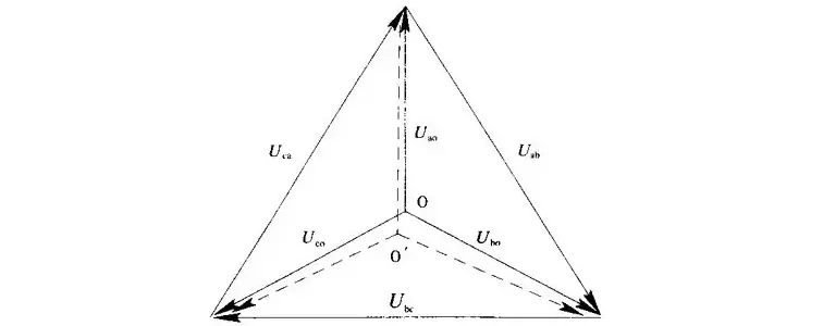
In transformers and generators, the neutral point is a specific point in the winding where the absolute voltage between this point and each external terminal is equal. In the diagram below, point O represents the neutral point.
II. Why Does the Neutral Point Need Grounding?
The electrical connection method between the neutral point and earth in a three-phase AC power system is called the neutral grounding method. This grounding method directly affects:
- The safety, reliability, and economics of the power grid;
- Selection of insulation levels for system equipment;
- Overvoltage levels;
- Relay protection schemes;
- Electromagnetic interference with communication lines.
Generally, the neutral grounding method of a power grid refers to the grounding configuration of transformer neutral points at various voltage levels in substations.
III. Classification of Neutral Grounding Methods
Before introducing specific grounding methods, two key concepts must be clarified: high-ground-fault-current systems and low-ground-fault-current systems.
- High-Ground-Fault-Current System: When a single-phase-to-ground fault occurs, the resulting ground fault current is very large. Examples include systems rated 110 kV and above, as well as 380/220 V three-phase four-wire systems. Also known as effectively grounded systems.
- Low-Ground-Fault-Current System: During a single-phase ground fault, no complete short-circuit loop is formed, so the fault current is much smaller than normal load current. Also known as non-effectively grounded systems.
Effectively grounded systems include:
- Solidly grounded neutral
- Neutral grounded through a resistor
Non-effectively grounded systems include:
- Ungrounded neutral
- Neutral grounded through an arc suppression coil (Petersen coil)
1. Solidly Grounded Neutral
Characteristics:
- A single-phase ground fault requires immediate tripping of the faulty equipment, interrupting power supply and reducing reliability.
- The large short-circuit current generates significant electrodynamic and thermal stress, potentially expanding damage.
- Strong magnetic fields from high fault currents cause electromagnetic interference to nearby communication and signaling circuits.
- During a single-phase fault, the faulted phase voltage drops to zero, while unfaulted phase voltages remain near normal phase voltage. Thus, equipment insulation can be designed for phase voltage only—reducing cost, especially beneficial at higher voltage levels.
Application:
Used in 110 kV and higher voltage systems.
2. Neutral Grounded Through a Resistor
This method is subdivided into:
- High-resistance grounding
- Medium-resistance grounding
- Low-resistance grounding
Advantages:
- Enables automatic fault clearance and simplifies operation/maintenance.
- Quickly isolates ground faults, resulting in low overvoltages, elimination of resonant overvoltages, and allowing use of lower-insulation-grade cables and equipment.
- Reduces insulation aging, extends equipment life, and improves reliability.
- Ground fault currents (hundreds of amperes or more) ensure high sensitivity and selectivity of relay protection—no need for complex fault line selection.
- Reduces risk of fire.
- Allows use of gapless ZnO surge arresters with high energy absorption and low residual voltage for overvoltage protection.
- Suppresses 5th harmonic components in arc grounding overvoltages, preventing escalation to phase-to-phase faults.
Application Scope:
- High-resistance grounding: Suitable for distribution networks with capacitive ground current <10 A, large generators where single-phase ground current exceeds allowable limits but remains <10 A. Resistance values typically range from hundreds to thousands of ohms.
- Medium- and low-resistance grounding: No strict boundary, but generally:
- Medium resistance: Neutral fault current between 10 A and 100 A
- Low resistance: Neutral fault current >100 A
These are used in urban distribution networks dominated by cables, power plant auxiliary systems, and large industrial plants—where capacitive currents are high and transient ground faults are rare.
3. Ungrounded Neutral
Characteristics:
- Single-phase ground fault current <10 A; arc self-extinguishes, and insulation may recover automatically.
- System symmetry is maintained; the system can operate temporarily with a fault to allow time for fault location.
- Minimal communication interference.
- Simple and economical.
- However, if capacitive current >10 A, high-magnitude intermittent arc grounding overvoltages may occur. These overvoltages are long-lasting, affect the entire network, and pose serious threats to equipment with weak insulation—especially rotating machines. Such overvoltages have repeatedly caused multi-point ground faults, equipment burnout, and major outages.
Resonant overvoltages frequently lead to blown fuses in voltage transformers (VTs), VT burnout, or even main equipment damage.
Application:
Suitable for overhead-line-dominated distribution networks with capacitive ground current <10 A, where 60–70% of single-phase faults are transient and immediate tripping is undesirable.
4. Neutral Grounded Through an Arc Suppression Coil (Petersen Coil)
Characteristics:
- The inductive current from the arc suppression coil compensates the system’s capacitive ground current, reducing fault current to <10 A—allowing arc self-extinction.
- Insulation at the fault point can recover automatically.
- Reduces the probability of intermittent arc grounding overvoltages.
- Maintains system symmetry during single-phase faults, enabling temporary continued operation for fault location.
- However, it only reduces the probability—not eliminates—the arc grounding overvoltage, and does not reduce its magnitude. The overvoltage multiplier remains high, posing significant insulation stress—especially dangerous for compact switchgear and cable systems, which may suffer insulation breakdown or phase-to-phase short circuits, leading to catastrophic equipment failure.
Application:
Used in overhead-line-dominated grids where capacitive ground current >10 A and transient single-phase faults are frequent.
IV. Application in Wind Farms
- The 110 kV or 220 kV high-voltage side of wind farms typically uses neutral grounding via a disconnector (isolator).
- The 35 kV collector system side usually employs arc suppression coil or resistor grounding.
- If the collector system uses all-cable lines, the capacitive current is relatively large; therefore, resistor grounding is recommended.