Advancements in Electromagnetic Induction-Based Cable Eccentricity Measurement: Overcoming Jitter and Enhancing Precision

A core challenge in online cable eccentricity measurement is the cable’s high - speed motion. This requires non - contact measurement equipment that can handle cable jitter. X - ray cable eccentricimeters, based on optical transmission imaging, measure multi - layer contour dimensions to calculate the geometric center of conductors relative to insulation eccentricity. However, they have drawbacks: slow measurement speed (only a few times per second), increased errors from cable jitter, and high costs.
1 Principle of Electromagnetic Induction - Based Cable Eccentricimeters
Electromagnetic induction - based cable eccentricimeters combine optical diameter measurement and electromagnetic induction for conductor detection. They measure the conductor’s electrical center (superior to geometric eccentricity), with a high speed of thousands of measurements per second. Faster measurement reduces jitter impacts, replacing X - ray devices in scenarios without multi - layer dimension requirements.
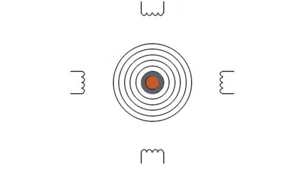
Current imported products (per public principles) use four inductive coils to detect magnetic fields (as in Figure 1). Some determine conductor centering via equal signal strength (adjusting the window with motors if unequal); others calculate the conductor center from detected signal strength.
2 Measurement Precision Control
Motor adjustment involves a process, inevitably causing lag. This leads to desynchronization between insulation and conductor measurements, creating delay errors—more severe cable jitter results in larger errors. In practice, this flaw manifests: if cable jitter occurs, eccentricity measurement results become unstable, with fluctuations exceeding 1%. This reflects equipment measurement error, not the actual cable condition.
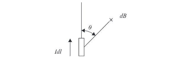
However, judging conductor centering by equal signal strength isn’t always valid. Biot - Savart’s Law states: the magnetic induction intensity (B) excited by a current element Idl at any point in space at distance r is:

This formula indicates that the magnetic induction intensity is inversely proportional to the square of the distance and proportional to the sine of the direction angle θ, as shown in Figure 2.
Based on this, a simulation calculation of the relationship between the magnetic field intensities at four points in space is carried out. For convenience, a model as shown in Figure 3 is established.
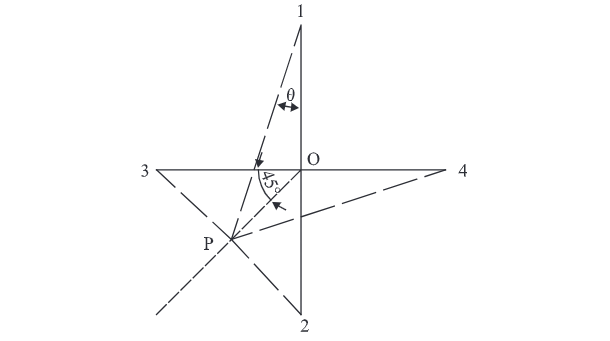
Points 1, 2, 3, and 4 are orthogonally and symmetrically distributed, with O as the center point. Let the current element move along the midline OP of axes 2 and 3. According to Formula (1), when the current element is at any point on OP, B1 = B4 and B2 = B3 hold. Thus, only the variation of B1/B2 with ∠θ needs to be examined. After calculation, a set of data is obtained, and a scatter trend graph is generated, as shown in Table 1 and Figure 4.
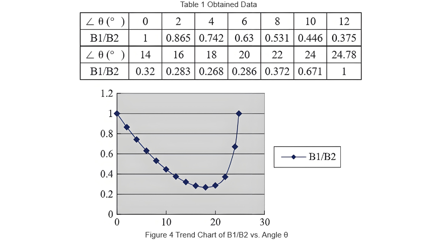
As seen in Figure 4, the trend is an irregular curve. As ∠θ increases, B1/B2 drops from 1 to ~0.268 (min), then rises back to 1. While magnetic fields at four points equalize, the current element is far from center O. In the interval, each value (except min) has two points—closer to min, points are nearer.
This applies to one quadrant, and the same holds for others. Relying on four - point magnetic field magnitudes can’t judge conductor centering or determine its center (magnetic field is a vector, not scalar).
Thus, to develop a better eccentricimeter, avoid blindly following foreign firms. A new principle: measure magnetic field direction angles θ₁, θ₂ at P₁/P₂ to determine source center O (Figure 5).
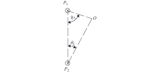
This principle is geometrically summarized as: A triangle is uniquely determined by one side and two adjacent included angles. While this holds, practical implementation requires high - speed, high - precision measurement of weak magnetic fields.
Cable conductors induce ~10mA current in external alternating fields. Sensors, spaced from cables, detect weak (~dozens of nT) fields—demanding high sensitivity, frequency response, and low noise (inherent noise impacts accuracy).
3 Implementation of Electromagnetic Induction - Based Eccentricimeters
Most imported products use coil sensors; this paper selects magnetoresistive sensors. Small - sized sensors integrate electromagnetic/optical measurements on the same cross - section (minimizing errors), with high inter - sensor consistency. Lithography - based magnetoresistive sensors are ideal.In contrast, imported coil - sensor products separate measurements, treating non - optical conductor segments as identical—increasing errors.
Magnetoresistive - based measurements: 1000/s measurements, ±2% repeatability (100–200nT), ±0.2% for 1000 - measurement averages, linearity <0.5%. Comparisons with imports are limited (no data).
Combining with fast LED×CCD optical measurement enables real - time eccentricity measurement (Figure 6).
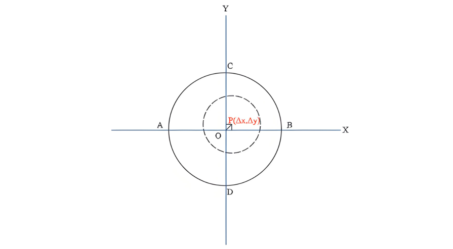
During each measurement, the positions of four points (A, B, C, D) on the insulation layer and the position of the conductor center point P are synchronously obtained. The eccentricities in the X and Y directions and the total eccentricity are calculated using the following formulas:

For each measurement, ex, ey, and e are averaged (over a set number of samples) as the final eccentricity result. To display concentricity, use Concentricity = 1 - Eccentricity. Δx/Δ y (X/Y - direction deviations) enable real - time extruder head adjustments for automatic cable eccentricity correction.
Faster measurement speeds reduce jitter errors: 1000 measurements/second achieve thousandth - place accuracy. Most imported products (hundreds of measurements/second) claim eccentricity accuracy assuming a centered conductor (matching outer - diameter precision, given as ±μm absolute values, not percentages—non - compliant).
3.1 LED×CCD Diameter Measurement
Based on telecentric optics, it uses light - blocking to create bright - dark CCD regions. Algorithms analyze edges to calculate dimensions. Global CCD exposure (simultaneous pixel sensing) causes jitter - induced edge blurring (vertical→slanted lines), but algorithms resolve edges and eliminate errors.
3.2 Optical Diameter Measurement Notes
Not the focus, but key: Cable eccentricity measurement requires real - time optical capture of four insulation - layer vertex positions (not just dimensions). Motor - scanned laser methods risk asynchronous - measurement errors. Thus, synchronizing optical and electromagnetic measurements is critical for instrument development.
4 Conclusion
The electromagnetic - induction - based instrument quickly measures the conductor’s electrical center, with low cost and advantages. Addressing imported products’ electromagnetic - measurement flaws, a novel photoelectromagnetic cable eccentricity meter is developed (thousandth - place accuracy).Technology evolves—future material advances will enable higher precision, driving industry progress.