• Product
  • Suppliers
  • Manufacturers
  • Solutions
  • Free tools
  • Knowledges
  • Experts
  • Communities
Search


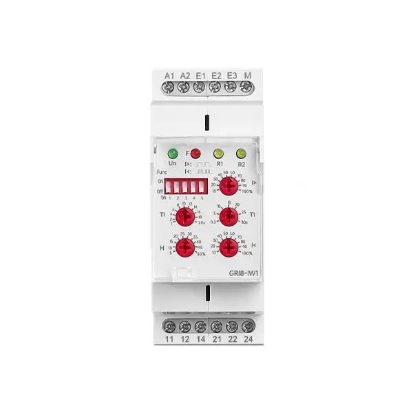
Time Relay Accuracy Measurement Method

Oliver Watts
Oliver Watts
Field: Inspection and testing
China

Accurate time relay measurement requires systematic steps to ensure reliable results. Before measurement, confirm the relay model, rated parameters, and operating environment, maintaining ambient temperature at 20±5°C and humidity below 85%RH. Prepare a high-precision timer (resolution 0.001s), regulated power supply (±1% fluctuation), standard load (matching contact rating), and digital multimeter.

Calibrate the timer and power supply, ensuring equipment error is within ±0.5%. Mount the relay on an insulated workbench and use a four-wire connection for control and measurement circuits to minimize contact resistance interference. Set target delay times—such as 5s, 30s, 60s—as test points. Apply rated voltage to the coil and use the timer to record the time difference between coil energization and contact closure or opening. Repeat each measurement at least five times.

A critical step is accurate contact state detection. Use an optocoupler isolation circuit to eliminate mechanical vibration interference. When the contact closes, the optocoupler’s output triggers the timer to start; when it opens, the signal drop stops timing. For solid-state relays, account for semiconductor turn-on voltage drop by adding a 0.5Ω sampling resistor in series to detect actual conduction timing.

time relay.jpg

Evaluate measurement error using both absolute and relative error. For example, if the set time is 10s and measurements are 10.12s, 10.09s, and 10.15s, the maximum absolute error is 0.15s and relative error is 1.5%. According to IEC 61812, industrial relays should have time error ≤±2%, and military-grade ≤±0.5%. If out-of-tolerance, check coil voltage stability, mechanical wear, or component aging.

Apply correction factors in special environments: compensate +0.3% per 10°C rise in temperature, and use double-shielded enclosures in strong electromagnetic fields. For digital relays with multi-range timing, verify switching accuracy across all ranges, especially carry-over errors during second-to-minute transitions. Reports must include environmental logs, raw waveform data, and correction calculations.

Calibration intervals depend on usage frequency: every three months for continuous-duty equipment, annually for intermittent use. Maintain historical data to create trend analysis and predict performance degradation. When systematic deviations occur, adjust variable resistors in the circuit or modify microcontroller timing code, then retest three times to verify correction. Final measurement data must be co-signed by a quality engineer and technician, and archived for five years.

Give a tip and encourage the author!
Recommended
A Guide to the Latest Transformer Testing Technologies
Transformers come in many types, primarily oil-immersed and dry-type. Their fault manifestations are diverse, but most failures are concentrated in the windings, core, connecting components, and oil contamination. For example, winding insulation damage, open circuits, short circuits, and inter-turn short circuits at connection points. Common external symptoms of transformer faults include severe overheating, excessive temperature rise, abnormal noise, and three-phase imbalance.Routine transforme
Oliver Watts
10/20/2025
Inspection of transformers can be performed without any detection tools.
Transformers are electrical devices that change voltage and current based on the principle of electromagnetic induction. In power transmission and distribution systems, transformers are essential for stepping up or stepping down voltages to reduce energy losses during transmission. For example, industrial facilities typically receive power at 10 kV, which is then stepped down to low voltage via transformers for on-site use. Today, let’s learn about several common transformer inspection methods.1
Oliver Watts
10/20/2025
Vacuum Circuit Breakers for Capacitor Bank Switching
Reactive Power Compensation and Capacitor Switching in Power SystemsReactive power compensation is an effective means to increase system operating voltage, reduce network losses, and improve system stability.Conventional Loads in Power Systems (Impedance Types): Resistance Inductive reactance Capacitive reactanceInrush Current During Capacitor EnergizationIn power system operation, capacitors are switched in to improve power factor. At the moment of closing, a large inrush current is generated.
Oliver Watts
10/18/2025
Vacuum Circuit Breaker Withstand Voltage Test Guide
Insulation Withstand Voltage Test Standards for Vacuum Circuit BreakersThe main purpose of the insulation withstand voltage test for vacuum circuit breakers is to verify whether the insulation performance of the equipment under high voltage is qualified, and to prevent breakdown or flashover accidents during operation. The test process must be strictly carried out in accordance with power industry standards to ensure equipment safety and power supply reliability.Test ObjectsThe test objects incl
Garca
10/18/2025
Related Products
Send inquiry
Download
Get the IEE Business Application
Use the IEE-Business app to find equipment, obtain solutions, connect with experts, and participate in industry collaboration anytime, anywhere—fully supporting the development of your power projects and business.