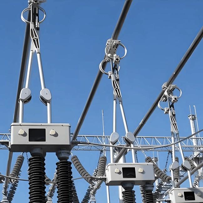
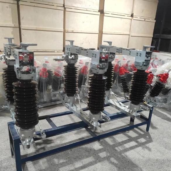
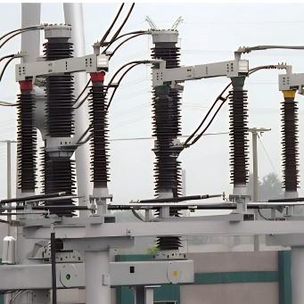
In power systems, high-voltage disconnectors in substations have suffered from aging infrastructure, severe corrosion, increasing defects, and insufficient current-carrying capacity of the main conductive circuit, significantly compromising power supply reliability. There is an urgent need to carry out technical retrofits on these long-in-service disconnectors. During such retrofits, to avoid interrupting customer power supply, the common practice is to place only the retrofit bay under maintenance while keeping adjacent bays energized. However, this operational mode often results in insufficient clearance between the equipment under retrofit and nearby live components, failing to meet the safety distance requirements for on-site lifting operations—posing significant challenges to normal maintenance work. Particularly when adjacent bays cannot be de-energized, large cranes are unable to perform lifting tasks due to spatial constraints.
To enable installation and maintenance of disconnectors in such complex environments, we have analyzed on-site challenges and propose the design and development of a specialized lifting device tailored for disconnector handling under constrained conditions, thereby providing robust support for power equipment maintenance.
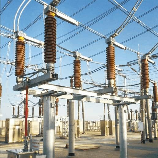
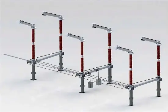
Based on design requirements and after reviewing various small crane configurations, and considering the specific 110 kV high-voltage disconnector installation environment, we determined that mounting the lifting machine directly onto the disconnector’s base structure offers superior stability, eliminates ground condition limitations, better adapts to complex sites, and enables rapid assembly and disassembly by a team of three personnel (as illustrated below).

I. Design of Crane Mechanisms
According to functional differences, crane mechanisms are categorized into four main systems: hoisting, traveling, slewing, and luffing mechanisms.
(1) Hoisting Mechanism
The hoisting mechanism comprises a drive unit, load handling device, wire rope reeving system, and auxiliary/safety devices. Power sources include electric motors or internal combustion engines. The wire rope system consists of wire ropes, drum assemblies, and a combination of movable and fixed pulleys. Load handling devices come in various forms—such as lifting eyes, spreader beams, hooks, electromagnetic lifters, and grabs. Considering design requirements and the disconnector lifting environment—and referencing commercially available small cranes—we selected a compact winch as the drive unit and a hook as the load handling device.
(2) Traveling Mechanism
The traveling mechanism adjusts the crane’s position horizontally to optimize working placement. It typically includes a traveling support system and a drive system. Our design employs a rail-guided support system, where steel wheels run along the channel steel of the disconnector base. This approach offers low rolling resistance, high load capacity, strong environmental adaptability, and ease of manufacturing and maintenance. Given the limited horizontal travel distance, the drive system is manually operated for simplicity.
(3) Slewing Mechanism
The slewing mechanism consists of a slewing bearing assembly and a slewing drive unit. The slewing bearing supports the rotating upper structure on the fixed vertical column, ensuring stable rotational motion and preventing overturning or detachment. The slewing drive provides torque for rotation and counteracts resistance forces during slewing.
(4) Luffing Mechanism
In jib-type cranes, the horizontal distance between the slewing centerline and the load handling device centerline is called "radius." The luffing mechanism adjusts this radius. Based on operational characteristics, luffing mechanisms are classified as either operational or non-operational.
Operational luffing occurs under load and is used to adjust radius during lifting—for example, to avoid collisions among multiple cranes or to precisely align with workstations—requiring higher luffing speeds to improve efficiency.
Non-operational luffing occurs without load, primarily to position the hook before lifting or to fold the boom for transport. Such operations are infrequent and use lower luffing speeds.
II. Weight Considerations of Lifting Equipment Components
Since this lifting device is a modular, portable small crane, component weight is critical. Excessive weight would hinder installation by a 2–3 person crew, potentially preventing successful deployment. Therefore, key components were fabricated from titanium alloy, with the heaviest single part weighing only 46 kg—enabling rapid assembly and disassembly by a small team.
III. Lifting Procedure
The lifting process for the high-voltage disconnector using this device is as follows:
First, workers place an insulated ladder against the channel steel of the disconnector base. From the ladder, they secure the crane’s base plate to the channel steel using guide-wheel clamping assemblies, with guide wheels engaged within the channel to prevent tipping or falling.
After base installation, two workers mount the crane’s boom support onto the SE7 slewing bearing, then fix the compact winch beneath it. Next, they sequentially assemble the main boom, auxiliary boom, and hydraulic cylinder. The hydraulic pump and control buttons are located at ground level. Once powered, operators can perform lifting operations entirely from the ground.
Additionally, the crane incorporates a triple safety protection system:
High-voltage proximity warning: An electric field sensor at the boom tip triggers voice alarms and automatic braking if the safe distance to adjacent live equipment is violated.
Overload protection: A strain sensor at the hook’s wire rope connection continuously monitors load weight and lifting angle; violations trigger alarms and automatic braking.
Power-loss protection: In case of sudden power failure during lifting, the system automatically locks to prevent load drop.
IV. Advantages of the Designed Lifting Device
Integrates electric field and strain sensors to provide real-time high-voltage proximity and overload voice warnings with automatic braking.
Features an electric slewing bearing base clamped to the truss structure, ensuring stable and controllable boom movement.
Main structural components (boom, column, base plate) use titanium alloy—offering corrosion resistance and significant weight reduction.
Modular design enables easy adaptation to various platforms, laying a foundation for future development and broader applications.
In summary, this lifting device uses titanium alloy for critical components to drastically reduce weight, features rational functional zoning for easy assembly/disassembly, and requires only three personnel for operation. It effectively solves the challenges posed by limited safety clearances and complex environments during high-voltage disconnector maintenance, demonstrating strong practicality and potential for widespread adoption.