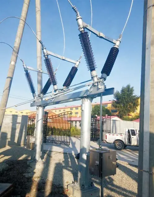
1. Operating Principle of the Disconnector
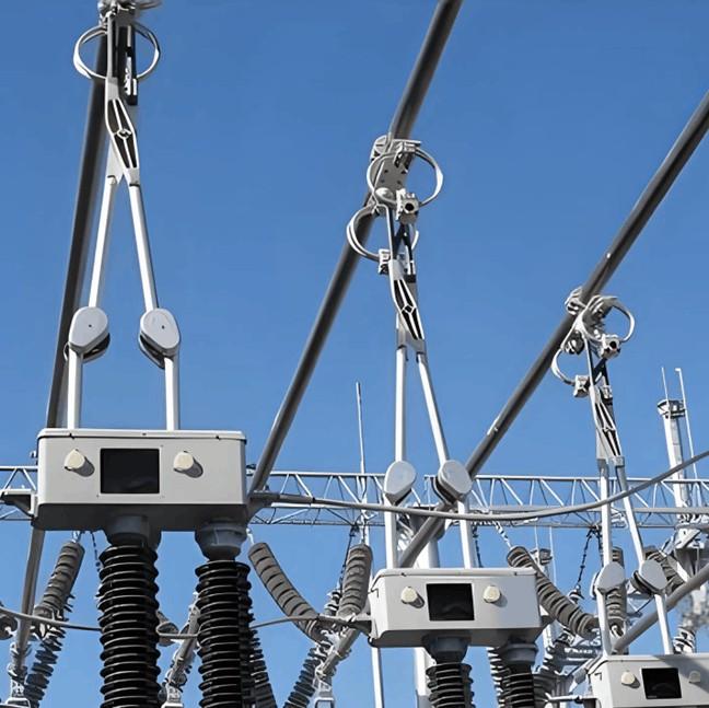
The operating mechanism of the disconnector is connected to the active pole of the disconnector via a connecting tube. When the main shaft of the mechanism rotates 90°, it drives the insulating pillar of the active pole to rotate 90°. The bevel gears inside the base drive the insulating pillar on the other side to rotate in the opposite direction, thereby achieving opening and closing operations. The active pole, through inter-pole linkage tubes, drives the other two passive poles to rotate, ensuring synchronized three-phase operation.
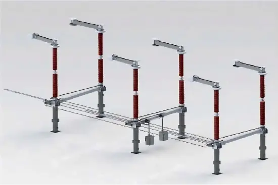
2. Operating Principle of the Earthing Switch
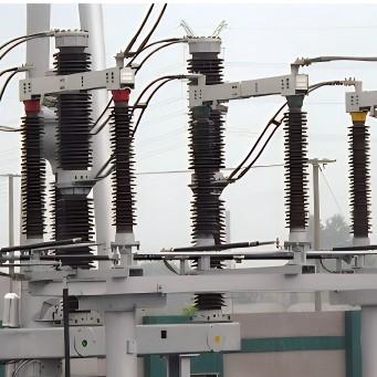
The main shafts of the three-phase earthing switch are connected together by horizontal connecting tubes via couplings. The handle of the operating mechanism rotates either 90° horizontally or 180° vertically, driving the connecting tubes to rotate through linkages, thus realizing the opening and closing operations of the earthing switch.
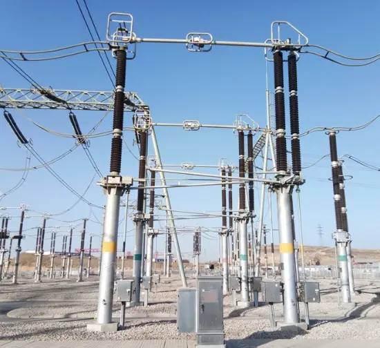
3. Operating Principle with Transmission Gearbox
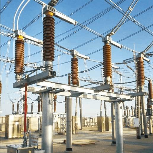
When equipped with a transmission gearbox installed horizontally, the gearbox can be positioned either between two poles or at either end of the three-pole assembly as required. The disconnector operating mechanism is mounted below and connected to the gearbox via water-gas pipes. When the main shaft of the mechanism rotates, the water-gas pipe connected to the gearbox drives one insulating pillar of the disconnector to rotate. At this moment, a pair of meshing bevel gears installed in the base drives the other insulating pillar to rotate, thereby ensuring consistent opening and closing actions of the left and right contact blades. Both opening and closing operations involve a rotation angle of 90°, and the terminal positions for open and closed states are determined by the mechanical limit devices of the disconnector.
4. Operating Principle with CS17-G Manual Operating Mechanism
When using the CS17-G manual operating mechanism, models CS17-G4, G5, and G6 are used for opening and closing the disconnector. Move the selector lever to the center position of the “E”-shaped slot, then rotate the mechanism handle 180° to perform the operation. After completion of opening or closing, move the lever from the center of the “E”-shaped slot to the slots at both ends marked “OPEN” or “CLOSE.” When using CS17-G1, G2, or G3 mechanisms to operate the earthing switch, the operating procedure is the same as for the disconnector, except that the mechanism handle is operated vertically.
5. Operating Principle with CS17-G Manual Operating Mechanism Equipped with Electromagnetic Lock
When using the CS17-G manual operating mechanism fitted with an electromagnetic lock, during operation first move the selector lever to the center position of the “E”-shaped slot, then press the button of the electromagnetic lock; simultaneously rotate the electromagnetic lock knob clockwise to its limit position so that the locking rod retracts from the locking hole. Then the mechanism handle can be rotated to perform opening or closing operations. After the operation is completed, the locking rod of the electromagnetic lock automatically resets, and finally the selector lever is moved to the locked position.
6. Operating Principle with CS17 Manual Operating Mechanism
When using the CS17 manual operating mechanism, the mechanism is directly connected via water-gas pipes and keyed universal joints to the shaft in the base of any one pole of the disconnector. During opening or closing operations, first place the handle of the mechanism in the horizontal position, then rotate it horizontally—clockwise rotation corresponds to closing, and counterclockwise rotation corresponds to opening. The open and closed positions of the disconnector are limited by the corresponding positions on the operating mechanism and the mechanical limit devices of the disconnector. After the operation is completed, raise the handle vertically and secure it with a locking ring.