What are the methods for handling single-phase grounding faults in the small-current grounding system of the distribution network?

Leon
08/01/2025

Current Status of Single-Phase Grounding Fault Detection
The low accuracy of single-phase grounding fault diagnosis in non-effectively grounded systems is attributed to several factors: the variable structure of distribution networks (such as looped and open-loop configurations), diverse system grounding modes (including ungrounded, arc-suppression coil grounded, and low-resistance grounded systems), the increasing annual ratio of cable-based or hybrid overhead-cable wiring, and complex fault types (like lightning strikes, tree flashovers, wire breakages, and personal electric shocks).
Classification of Grounding Faults
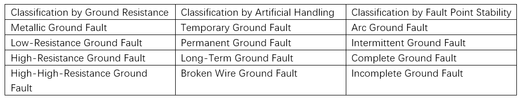
Faults in the power grid can involve metallic grounding, lightning discharge grounding, tree branch grounding, resistance grounding, and poor insulation grounding. They can also include various arc grounding scenarios, such as short-gap discharge arcs, long-gap discharge arcs, and intermittent arcs. The fault signal characteristics exhibited by different grounding conditions vary in form and magnitude.
Grounding Fault Handling Technologies
  • Arc-suppression compensation technology and personal electric shock protection
  • Overvoltage suppression
  • Fault line selection and phase selection, fault section location, and precise fault location
  • Relay protection: Fault removal
  • Feeder automation: Fault isolation and automatic power supply restoration

Difficulties in Grounding Faults

  • Different neutral point grounding methods
  • Different grounding attributes: Variable grounding forms
  • Different line types: Overhead lines, cable lines, and hybrid overhead-cable lines
  • Different fault locations and fault occurrence times

Complexity of Grounding Fault Characteristics

  • Small grounding current; residual current in resonant grounding is less than 10 A.
  • The compensation current of the arc-suppression coil causes the zero-sequence current of the fault line to have a smaller amplitude than that of non-fault lines, with the same direction.
  • Intermittent grounding with unstable arcs; approximately 10% of faults involve intermittent grounding.
  • A high proportion of high-resistance (resistance above 1,000 ohms) faults, accounting for about 5%. Even with low-resistance grounding, it is difficult to detect high-resistance faults.
  • Main causes of distribution network electric shock faults: ① The human body touches or approaches normally operating conductors; ② Conductors fall to the ground. Both human electric shocks and conductor-to-ground faults involve high grounding resistance. Thus, electric shock protection in distribution networks is also a high-resistance grounding fault protection issue.
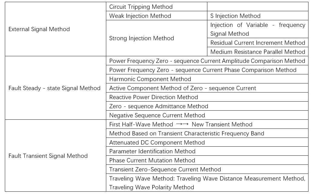
Methods for Locating Single-Phase Grounding Faults
There are currently three categories, totaling 20 basic methods, for locating single-phase grounding faults:
Artificial intelligence (AI) is a cutting-edge technology in the development of modern technology. It establishes corresponding theoretical models by simulating the characteristics of humans, animals, or plants, and solves problems using "human-like" thinking. Especially for power grids, which are inherently highly nonlinear systems, they fall within the scope of AI applications. Additionally, the use of computer computing enhances operational speed, enabling the solution of complex systems like power grids.
  • Expert Database: Establish a database that integrates relevant knowledge and experience.
  • Artificial Neural Network: Simulates the operation of human neurons to solve problems, functioning as a highly nonlinear system.
  • Ant Colony Optimization: An algorithm that simulates the biological behavior of ants searching for food to solve the traveling salesman problem.
  • Genetic Algorithm: Simulates the biological evolution process to obtain global optimal or suboptimal solutions.
  • Petri Net: Models interrelated components in a system, describing phenomena where related components change in chronological order.
  • Rough Set Theory: Uses more information than the system requires as input to ensure a comprehensive description of the system's operational status.
Most intelligent algorithms remain in the theoretical stage, with only a few having been practically applied. However, AI algorithms have demonstrated their superiority in the new era.
Leon

Hello! I'm Leon, with 20 years of extensive experience in the power industry. My expertise spans from power distribution equipment to grid operations and maintenance, grounded in robust hands-on and theoretical knowledge. Currently, I focus on sharing insights into electrical equipment fault diagnosis, demystifying complex technical challenges through accessible explanations. I welcome collaboration with industry peers and enthusiasts to collectively explore the intricacies of the power sector.

Neutral line current is actually greater than live line current? Why?
In a three-phase four-wire power distribution system, it is a consensus among industry insiders that the neutral line current should be very small when the three-phase loads are balanced. However, more and more phenomena are subverting this concept.For example, the advertising light boxes around a building use fluorescent lighting with electronic ballasts. The loads on the three-phase lines are balanced, with each phase current being approximately 90A, but the neutral line current reaches 160A.I
RW Energy
08/01/2025
Difference Between EMF and Voltage
One of the key differences between electromotive force (EMF) and voltage is that EMF refers to the energy supplied to charges, while voltage represents the energy required to move a unit charge from one point to another. Other distinctions between the two are detailed in the comparison chart below.Comparison ChartDefinition of VoltageVoltage is defined as the energy required to move a unit charge from one point to another. It is measured in volts (V) and denoted by the symbolV. Voltage is induce
Dyson
08/01/2025
What should be done if the neutral line current is too large?
As we all know, if an electrical line exceeds its rated load, it will overheat severely, and may even cause a fire. For safety reasons, overcurrent protection devices are therefore installed on lines. Whenever the current in the line exceeds the rated value, the overcurrent protection device will automatically cut off the line to prevent fire. The "excessive neutral line current" mentioned here refers to the phenomenon where the neutral line current is excessively high (more than 1.5 times the p
RW Energy
08/01/2025
Estimation of capacitive current
The capacitive current is mainly determined by the length of the feeder, the cross-sectional area of the conductor, the dielectric constant, the height above the ground, and the rated voltage. The specific estimation methods are as follows:Estimation of capacitive current of overhead lines: For overhead lines of 3 - 35 kV, the capacitance per phase to ground is usually 5000 - 6000 pF/km. Based on this, the value of the single-phase grounding capacitive current per kilometer for lines of differen
Leon
07/31/2025
Inquiry
Download
IEE-Business is dedicated to serving the personnel in the global power industry.
Join IEE-Business, not only can you discover power equipment and power knowledge, but also canhnd like - minded friends!