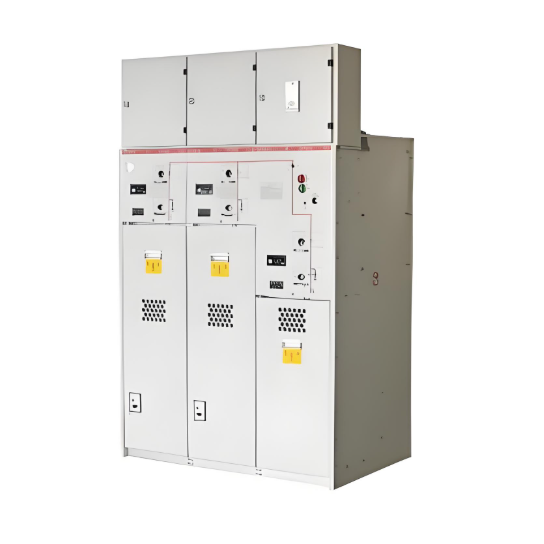
Ang solid insulated ring main unit (RMU) mao ang usa ka bag-ong gamit sa distribusyon nga nagpadayon sa external solid encapsulation, insulated busbar, ug compact combined unit technology. Ang mga switch ug high-voltage live components niini gibutang pila sa epoxy resin, nga gisilbing primary insulation tali sa live parts ug ground, ug tali sa phases. Isip usa ka eco-friendly alternative sa SF₆ gas-insulated equipment, ang 12kV solid insulated RMU naggahin og mga advantage apan naturalgad mahimong magdugay sa pag-disperse sa heat.
Sa gi-study na 12kV solid insulated RMU, ang main conductive loops gibutang pila sa epoxy ug silicone rubber materials. Habang ang disconnecting switch nagamit og air insulation, adunay labi ka dako ug sealed space nga may dugay sa pag-disperse sa heat. Kini nagpadayon sa pag-lampa sa temperature rise limits. Ang matagal nga exposure sa mataas nga temperatura mahimong makapadasig sa mga materyales sa produksyon ug mapabilin sa thermal aging. Kini nagpakita og pagbawas sa insulating performance sa produkto, resulta mao ang pagbawas sa kabuok nga kalidad ug reliability. Sa severe cases, kini mahimong mogensera og electrical accidents, nga makapadisrupt sa normal nga operasyon.
Gihatagan ang critical importance ug inherent difficulty sa pag-address sa issue sa temperature rise, naging focus sa intense research. Gipatuloy ang structural optimizations aron mapataas ang temperature rise margin, asigurado ang long-term stable operation sa produkto. Ang insulation sa solid insulated RMU primariliya nagamit ang combination sa air ug solid insulation. Ang prototype batasan sa initial design gi-test sa temperature rise research. Ang key test point data gitakda sa Table 1.
|
No. |
Measurement Point Location |
Standard (K) |
Equilibrium Temp. (°C) |
Temp. Rise (K) |
Margin from Std. (K) |
Remark |
|
1 |
A-phase Disconnect Knife Pivot |
65.0 |
86.1 |
73.0 |
-8.0 |
Exceeded |
|
2 |
A-phase Disconnect Knife Tip |
65.0 |
78.2 |
65.1 |
-1.1 |
Exceeded |
|
3 |
B-phase Disconnect Knife Pivot |
65.0 |
86.4 |
73.3 |
-8.3 |
Exceeded |
|
4 |
B-phase Disconnect Knife Tip |
65.0 |
88.0 |
74.9 |
-9.9 |
Exceeded |
|
5 |
C-phase Disconnect Knife Pivot |
65.0 |
80.6 |
67.5 |
-2.5 |
Exceeded |
|
6 |
C-phase Disconnect Knife Tip |
65.0 |
81.6 |
68.5 |
-3.5 |
Exceeded |
Tali sa Table 1, ang temperature rise testing sa prototype batasan sa initial design nagsulti sa severe exceedances sa limits sa tanang disconnecting knife pivots ug tips. Aron masolbaran kini, ang optimization efforts gitumong sa sumala nga duha ka aspects:
Magnetothermal Coupling Simulation
Tungod kay ang applied current adunay kurang sa 1000A, kini nga simulation solamente modelled ang joule heating generated sa loop resistance sa conductive path. Ang simulated temperature distribution directly reflects joule heating effects, excluding scenarios involving heat dissipation through radiation or convection. Kini naghatag og results nga suitable sa pag-analyze sa impact sa structure sa conductor sa temperature distribution. Key product technical parameters gitakda sa Table 2.
|
No. |
Parameter Name |
Value |
|
1 |
Rated Voltage (kV) |
12 |
|
2 |
Rated Current (A) |
700 |
|
3 |
A-phase Loop Resistance (μΩ) |
190 (Assumed) |
|
4 |
B-phase Loop Resistance (μΩ) |
190 (Assumed) |
|
5 |
C-phase Loop Resistance (μΩ) |
190 (Assumed) |
Simulation Results
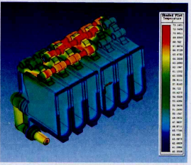
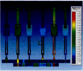
Figure 1 shows the magnetothermal coupling temperature distribution of the insulation module. Figure 2 shows the overall magnetothermal coupling temperature distribution of the internal conductive path. Magnetothermal coupling simulation using ANSOFT software revealed that the primary locations of elevated heat generation were the tips of the disconnecting knives and the contact points with the stationary contacts. The B-phase disconnecting knife, in particular, exhibited consistently higher temperatures. Structural optimization is required to reduce constriction resistance and homogenize the conductive cross-sectional area.
Cabinet-Level Thermal Simulation
Cabinet-level thermal simulation using ICEPAK software examined the distribution and forms of heat dissipation from the conductive paths after current flow, as well as the impact of the enclosure on heat transfer.
Technical Requirements
The temperature rise standard follows GB/T 11022-2011 "Common specifications for high-voltage switchgear and controlgear standards." As stipulated by the relevant standards:
Software Settings
Initial Temperature: 20°C; Three-phase current phase angles: 0°, 120°, -120°.
Simulation Results
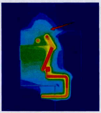
The cabinet-level thermal simulation results (Figure 4) showed that due to the small clearance between the top plate of the sealed enclosure and the upper part of the insulation module, the effective heat dissipation area on the upper part of the cabinet is very limited. Consequently, heat concentrates at the top, making it difficult to dissipate, leading to persistently high busbar temperature rise. To provide more heat dissipation space within the sealed cabinet, the cabinet height was increased and a heat-dissipating coating was applied to its inner surfaces.
Temperature Rise Test After Structural Optimization
Following the simulation studies and initial temperature rise test findings, modifications were made to the cabinet and certain components. A subsequent temperature rise test was conducted (refer to Table 4).
|
No. |
Measurement Point Location |
Standard (K) |
Equilibrium Temp. (°C) |
Temp. Rise (K) |
Margin from Std. (K) |
Remark |
|
1 |
A-phase Disconnect Knife Pivot |
65.0 |
72.4 |
55.2 |
+9.8 |
Compliant |
|
2 |
A-phase Disconnect Knife Tip |
65.0 |
73.7 |
56.5 |
+8.5 |
Compliant |
|
3 |
B-phase Disconnect Knife Pivot |
65.0 |
73.6 |
56.4 |
+8.6 |
Compliant |
|
4 |
B-phase Disconnect Knife Tip |
65.0 |
73.6 |
56.4 |
+8.6 |
Compliant |
|
5 |
C-phase Disconnect Knife Pivot |
65.0 |
69.6 |
52.4 |
+12.6 |
Compliant |
|
6 |
C-phase Disconnect Knife Tip |
65.0 |
70.7 |
53.5 |
+11.5 |
Compliant |
As shown in Table 4, the temperature rise values for the prototype retested are now compliant with requirements. Furthermore, a design margin of at least 8.5 K has been achieved.
Subsequent Optimization and Rectification
Given the critical importance of temperature rise and the potential consequences of non-compliance, further optimization is warranted to enhance prototype performance, even after meeting the standard. The goal is to achieve a controlled temperature rise margin between 12 K and 15 K. For instance, specific modifications on the insulation module require testing (Original Table 5 was incomplete; logically incorporated). Simulation results suggest that optimizing the structure of the main insulation module creates a more reasonable internal heat dissipation pathway, offering significant potential for further reducing the overall internal conductive loop temperature rise. This potential requires further experimental validation.
Conclusion
A combined design approach utilizing computer simulation technology and temperature rise testing enabled structural optimization of the solid insulated ring main unit. The optimized product complies with the temperature rise requirements stipulated in GB/T 11022-2011 "Common specifications for high-voltage switchgear and controlgear standards" and achieves a significant safety margin.


