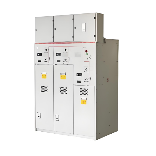
Ang solid insulated ring main unit (RMU) ay isang bagong kagamitan sa pamamahagi na naglalaman ng panlabas na solid encapsulation, insulated busbar, at compact combined unit technology. Ang mga switch nito at high-voltage live components ay buong embedded sa epoxy resin, na siyang pangunahing insulasyon sa pagitan ng mga live parts at lupa, at sa pagitan ng mga phase. Bilang isang eco-friendly na alternative sa SF₆ gas-insulated equipment, ang 12kV solid insulated RMU ay nagbibigay ng mga benepisyo ngunit may mahinang heat dissipation characteristics.
Sa pinag-aaralan na 12kV solid insulated RMU, ang mga pangunahing conductive loops ay nakakalat sa epoxy at silicone rubber materials. Habang ang disconnecting switch ay gumagamit ng air insulation, ito ay nasa napakaliit at sealed na espasyo na may mahinang heat dissipation conditions. Dahil dito, ito ay madaling lumampas sa temperature rise limits. Ang matagal na pagkalantad sa mataas na temperatura ay maaaring magdulot ng pagbabago sa anyo ng mga materyales ng kagamitan at thermal aging. Ito ay nagbabawas ng insulation performance ng produkto, na humahantong sa pagbaba ng kabuuang kalidad at reliabilidad ng produkto. Sa mas malubhang kaso, ito ay maaaring mag-trigger ng electrical accidents, na nagbabanta sa normal na operasyon.
Dahil sa kritikal na importansya at inherent na kahirapan ng pagtugon sa isyu ng temperature rise, ito ay naging focus ng intense na pagsasaliksik. Ang mga structural optimizations ay patuloy na inilapat upang taasan ang temperature rise margin, na nagpapatiyak ng matagal na stable na operasyon ng produkto. Ang insulation ng solid insulated RMU ay pangunahing gumagamit ng combination ng air at solid insulation. Ang isang prototype batay sa unang disenyo ay sumailalim sa temperature rise research testing. Ang key test point data ay ipinapakita sa Table 1.
|
No. |
Measurement Point Location |
Standard (K) |
Equilibrium Temp. (°C) |
Temp. Rise (K) |
Margin from Std. (K) |
Remark |
|
1 |
A-phase Disconnect Knife Pivot |
65.0 |
86.1 |
73.0 |
-8.0 |
Exceeded |
|
2 |
A-phase Disconnect Knife Tip |
65.0 |
78.2 |
65.1 |
-1.1 |
Exceeded |
|
3 |
B-phase Disconnect Knife Pivot |
65.0 |
86.4 |
73.3 |
-8.3 |
Exceeded |
|
4 |
B-phase Disconnect Knife Tip |
65.0 |
88.0 |
74.9 |
-9.9 |
Exceeded |
|
5 |
C-phase Disconnect Knife Pivot |
65.0 |
80.6 |
67.5 |
-2.5 |
Exceeded |
|
6 |
C-phase Disconnect Knife Tip |
65.0 |
81.6 |
68.5 |
-3.5 |
Exceeded |
Bilang ipinapakita sa Table 1, ang temperature rise testing sa prototype batay sa unang disenyo ay nagpakita ng malubhang paglalampas sa limits sa parehong disconnecting knife pivots at tips. Upang tugunan ito, ang mga optimization efforts ay naka-focus sa sumusunod na dalawang aspeto:
Magnetothermal Coupling Simulation
Dahil ang applied current ay mas mababa kaysa 1000A, ang simulation na ito ay eksklusibong model ng joule heating na gawa ng loop resistance sa conductive path. Ang simulated temperature distribution ay direktang nagpapakita ng joule heating effects, na hindi kasama ang scenarios na may heat dissipation sa pamamagitan ng radiation o convection. Ito ay nagpapahintulot sa resulta na maging suitable para sa analisis ng impact ng conductor structure sa temperature distribution. Ang key product technical parameters ay ipinapakita sa Table 2.
|
No. |
Parameter Name |
Value |
|
1 |
Rated Voltage (kV) |
12 |
|
2 |
Rated Current (A) |
700 |
|
3 |
A-phase Loop Resistance (μΩ) |
190 (Assumed) |
|
4 |
B-phase Loop Resistance (μΩ) |
190 (Assumed) |
|
5 |
C-phase Loop Resistance (μΩ) |
190 (Assumed) |
Simulation Results
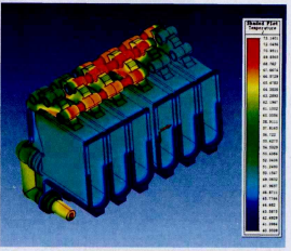
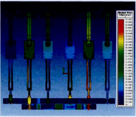
Ang Figure 1 ay nagpapakita ng magnetothermal coupling temperature distribution ng insulation module. Ang Figure 2 naman ay nagpapakita ng overall magnetothermal coupling temperature distribution ng internal conductive path. Ang magnetothermal coupling simulation gamit ang ANSOFT software ay nagpakita na ang primary locations ng elevated heat generation ay ang tips ng disconnecting knives at ang contact points sa stationary contacts. Partikular na ang B-phase disconnecting knife ay nagpakita ng consistent na mas mataas na temperatura. Kailangan ng structural optimization upang bawasan ang constriction resistance at homogenize ang conductive cross-sectional area.
Cabinet-Level Thermal Simulation
Ang cabinet-level thermal simulation gamit ang ICEPAK software ay nag-examine ng distribution at forms ng heat dissipation mula sa conductive paths pagkatapos ng pag-flow ng current, at ang impact ng enclosure sa heat transfer.
Technical Requirements
Ang temperature rise standard ay sumusunod sa GB/T 11022-2011 "Common specifications for high-voltage switchgear and controlgear standards." Ayon sa relevant na standards:
Software Settings
Initial Temperature: 20°C; Three-phase current phase angles: 0°, 120°, -120°.
Simulation Results
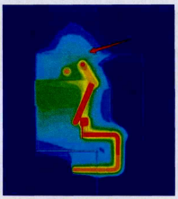
Ang cabinet-level thermal simulation results (Figure 4) ay nagpakita na dahil sa maliit na clearance sa pagitan ng top plate ng sealed enclosure at ang upper part ng insulation module, ang effective heat dissipation area sa upper part ng cabinet ay napakaliit. Dahil dito, ang heat ay nag-concentrate sa tuktok, na nagiging mahirap ilabas, na nagresulta sa persistently high busbar temperature rise. Upang bigyan ng mas maraming heat dissipation space sa loob ng sealed cabinet, ang cabinet height ay itinaas at isinama ang heat-dissipating coating sa inner surfaces nito.
Temperature Rise Test After Structural Optimization
Pagkatapos ng simulation studies at initial temperature rise test findings, ginawa ang mga modification sa cabinet at ilang components. Isinagawa ang subsequent temperature rise test (refer to Table 4).
|
No. |
Measurement Point Location |
Standard (K) |
Equilibrium Temp. (°C) |
Temp. Rise (K) |
Margin from Std. (K) |
Remark |
|
1 |
A-phase Disconnect Knife Pivot |
65.0 |
72.4 |
55.2 |
+9.8 |
Compliant |
|
2 |
A-phase Disconnect Knife Tip |
65.0 |
73.7 |
56.5 |
+8.5 |
Compliant |
|
3 |
B-phase Disconnect Knife Pivot |
65.0 |
73.6 |
56.4 |
+8.6 |
Compliant |
|
4 |
B-phase Disconnect Knife Tip |
65.0 |
73.6 |
56.4 |
+8.6 |
Compliant |
|
5 |
C-phase Disconnect Knife Pivot |
65.0 |
69.6 |
52.4 |
+12.6 |
Compliant |
|
6 |
C-phase Disconnect Knife Tip |
65.0 |
70.7 |
53.5 |
+11.5 |
Compliant |
Bilang ipinapakita sa Table 4, ang temperature rise values para sa prototype retested ay ngayon compliant sa requirements. Bukod dito, natamo na ang design margin ng hindi bababa sa 8.5 K.
Subsequent Optimization and Rectification
Dahil sa critical na importansya ng temperature rise at ang potential na consequences ng non-compliance, kinakailangan pa rin ng further optimization upang i-enhance ang performance ng prototype, kahit na matapos ma-meet ang standard. Ang layunin ay makamit ang controlled temperature rise margin sa pagitan ng 12 K at 15 K. Halimbawa, ang specific modifications sa insulation module ay nangangailangan ng testing (Original Table 5 was incomplete; logically incorporated). Ang simulation results ay nagmumungkahi na ang pag-optimize ng structure ng main insulation module ay nagbibigay ng mas reasonable na internal heat dissipation pathway, na nagbibigay ng significant potential para sa further reduction ng overall internal conductive loop temperature rise. Ito ay nangangailangan pa ng experimental validation.
Conclusion
Ang combined design approach na gumagamit ng computer simulation technology at temperature rise testing ay nag-enable ng structural optimization ng solid insulated ring main unit. Ang optimized product ay compliant sa temperature rise requirements na nasa GB/T 11022-2011 "Common specifications for high-voltage switchgear and controlgear standards" at nakakamit ng significant safety margin.


