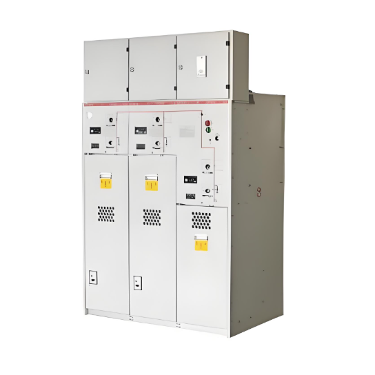
Kitambulisho chenye kifuniko cha solid insulated ring main unit (RMU) ni vifaa vya kirenga vya mpya vinavyojumuisha teknolojia ya encapsulation nje, insulated busbar, na teknolojia ya combined unit. Vifaa hivi vina switches na majanga ya kiwango cha juu yote vilivyofanikiwa kwenye epoxy resin, ambayo inaendeleza kuwa insulation kuu kati ya majanga na ardhi, na kati ya fasi. Kama alternative zenye afya za mazingira ya vifaa vya SF₆ gas-insulated, RMU ya 12kV ya solid insulated inatoa faida lakini ina uwezo wa kupata sifa mbaya za heat dissipation.
Katika RMU ya 12kV ya solid insulated iliyotajwa, mikoa maalum ya kutumia umeme yamefanikiwa kwenye zipu na silicone rubber. Ingawa disconnecting switch hutumia air insulation, inaishi katika eneo la ukuta zaidi na lililo kufunga na sifa mbaya za heat dissipation. Hii inafanya iwe na uwezo mkubwa wa kupanda temperature rise limits. Ukosefu wa muda wa joto unaweza kusababisha materials ya kujenga vifaa kunyoka na kuathiri thermal aging. Ukweli huu unapunguza performance ya insulation ya bidhaa, kufanya ubora na uhakika wa bidhaa kuvunjika. Katika matukio magumu, inaweza kusababisha ajali za umeme, kusababisha upimaji wa kazi ya kawaida.
Kwa sababu ya muhimu na ukuaji wa kujibu temperature rise issue, iliwa kuwa kitu kikuu cha utafiti. Maendeleo ya structure zilizofanyika mara kwa mara kusaidia kwa kuboresha temperature rise margin, husika kwamba bidhaa itegekeze kwa muda mrefu. Insulation ya RMU ya solid insulated huwa inatumia combination ya air na solid insulation. Prototype iliyobuni kulingana na mtaani uliyofanikiwa aliyopimwa kwa ajili ya temperature rise research testing. Data ya muhimu ya test point inaonyeshwa kwenye Table 1.
|
No. |
Measurement Point Location |
Standard (K) |
Equilibrium Temp. (°C) |
Temp. Rise (K) |
Margin from Std. (K) |
Remark |
|
1 |
A-phase Disconnect Knife Pivot |
65.0 |
86.1 |
73.0 |
-8.0 |
Exceeded |
|
2 |
A-phase Disconnect Knife Tip |
65.0 |
78.2 |
65.1 |
-1.1 |
Exceeded |
|
3 |
B-phase Disconnect Knife Pivot |
65.0 |
86.4 |
73.3 |
-8.3 |
Exceeded |
|
4 |
B-phase Disconnect Knife Tip |
65.0 |
88.0 |
74.9 |
-9.9 |
Exceeded |
|
5 |
C-phase Disconnect Knife Pivot |
65.0 |
80.6 |
67.5 |
-2.5 |
Exceeded |
|
6 |
C-phase Disconnect Knife Tip |
65.0 |
81.6 |
68.5 |
-3.5 |
Exceeded |
Kama inavyoelezea kwenye Table 1, temperature rise testing ya prototype iliyobuni kulingana na mtaani uliyofanikiwa ulipatikana kuwa na exceedances kali kwa pamoja ya disconnecting knife pivots na tips. Kusaidia tatizo hili, maendeleo ya optimization yalikuwa yanayofokusiana kwenye viwango vifuatavyo:
Magnetothermal Coupling Simulation
Tangu current iliyotumika ilikuwa chache kuliko 1000A, simulation hii iliyotumika tu ilianza joule heating iliyotokana na loop resistance kwenye conductive path. Distribution ya temperature iliyosimuliwa inaonyesha matokeo ya joule heating tu, bila kuhusu scenarios za heat dissipation kwa njia ya radiation au convection. Hii huchukua matokeo sawa sawa kwa kutathmini impact ya structure ya conductor kwenye distribution ya temperature. Technical parameters muhimu za bidhaa zimeorodheshwa kwenye Table 2.
|
No. |
Parameter Name |
Value |
|
1 |
Rated Voltage (kV) |
12 |
|
2 |
Rated Current (A) |
700 |
|
3 |
A-phase Loop Resistance (μΩ) |
190 (Assumed) |
|
4 |
B-phase Loop Resistance (μΩ) |
190 (Assumed) |
|
5 |
C-phase Loop Resistance (μΩ) |
190 (Assumed) |
Simulation Results
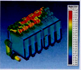
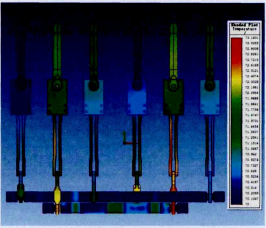
Figure 1 inaelezea magnetothermal coupling temperature distribution ya insulation module. Figure 2 inaelezea magnetothermal coupling temperature distribution kamili ya conductive path ndani. Magnetothermal coupling simulation using ANSOFT software ilipatikana kuwa primary locations za heat generation high ilikuwa tips ya disconnecting knives na points za contact na stationary contacts. B-phase disconnecting knife hasa ilikuwa na temperature high consistently. Structural optimization inahitajika kuboresha constriction resistance na homogeneous conductive cross-sectional area.
Cabinet-Level Thermal Simulation
Cabinet-level thermal simulation using ICEPAK software ilipimia distribution na forms za heat dissipation kutoka kwenye conductive paths baada ya current flow, na impact ya enclosure kwenye heat transfer.
Technical Requirements
Temperature rise standard inaenda kwa GB/T 11022-2011 "Common specifications for high-voltage switchgear and controlgear standards." Kulingana na standards zinazohusika:
Software Settings
Initial Temperature: 20°C; Three-phase current phase angles: 0°, 120°, -120°.
Simulation Results
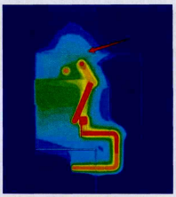
Cabinet-level thermal simulation results (Figure 4) showed that due to the small clearance between the top plate of the sealed enclosure and the upper part of the insulation module, the effective heat dissipation area on the upper part of the cabinet is very limited. Consequently, heat concentrates at the top, making it difficult to dissipate, leading to persistently high busbar temperature rise. To provide more heat dissipation space within the sealed cabinet, the cabinet height was increased and a heat-dissipating coating was applied to its inner surfaces.
Temperature Rise Test After Structural Optimization
Following the simulation studies and initial temperature rise test findings, modifications were made to the cabinet and certain components. A subsequent temperature rise test was conducted (refer to Table 4).
|
No. |
Measurement Point Location |
Standard (K) |
Equilibrium Temp. (°C) |
Temp. Rise (K) |
Margin from Std. (K) |
Remark |
|
1 |
A-phase Disconnect Knife Pivot |
65.0 |
72.4 |
55.2 |
+9.8 |
Compliant |
|
2 |
A-phase Disconnect Knife Tip |
65.0 |
73.7 |
56.5 |
+8.5 |
Compliant |
|
3 |
B-phase Disconnect Knife Pivot |
65.0 |
73.6 |
56.4 |
+8.6 |
Compliant |
|
4 |
B-phase Disconnect Knife Tip |
65.0 |
73.6 |
56.4 |
+8.6 |
Compliant |
|
5 |
C-phase Disconnect Knife Pivot |
65.0 |
69.6 |
52.4 |
+12.6 |
Compliant |
|
6 |
C-phase Disconnect Knife Tip |
65.0 |
70.7 |
53.5 |
+11.5 |
Compliant |
As shown in Table 4, the temperature rise values for the prototype retested are now compliant with requirements. Furthermore, a design margin of at least 8.5 K has been achieved.
Subsequent Optimization and Rectification
Given the critical importance of temperature rise and the potential consequences of non-compliance, further optimization is warranted to enhance prototype performance, even after meeting the standard. The goal is to achieve a controlled temperature rise margin between 12 K and 15 K. For instance, specific modifications on the insulation module require testing (Original Table 5 was incomplete; logically incorporated). Simulation results suggest that optimizing the structure of the main insulation module creates a more reasonable internal heat dissipation pathway, offering significant potential for further reducing the overall internal conductive loop temperature rise. This potential requires further experimental validation.
Conclusion
A combined design approach utilizing computer simulation technology and temperature rise testing enabled structural optimization of the solid insulated ring main unit. The optimized product complies with the temperature rise requirements stipulated in GB/T 11022-2011 "Common specifications for high-voltage switchgear and controlgear standards" and achieves a significant safety margin.


