Para asegurar la alta kalidad ug performance sa materyales, disenyo, ug asambla sa bawat AC circuit breaker, ang mga manugopanon naglakip og rutinong pagsumala sa tanang unit nga giprodukt. Ang mga sumala kini mahimong importante aron masigurado ang reliability ug seguridad sa mga circuit breakers, nagsunod sila sa ilang pagtrabaho sa gispezifikar nga kondisyon.
Sa multi-phase circuit breakers nga gilangkoban sa daghang breaker units (tulad sa V-type o T-type configurations), ang rutinong pagsumala isip transport units nga fully assembled. Ang mga transport units, nga gilangkoban sa column insulators ug breaker units, gi-mount sa usa ka specially designed frame aron maconnect sa operating mechanism. Kini nga custom frame dili lang molihok sa electrical connections sa panahon sa pagsumala, apan usab iya ang actual working conditions sa circuit breaker sa oras sa pag-install on-site, masiguro ang accuracy ug reliability sa resulta sa pagsumala.
Ang sumusunod mao ang rutinong testing items sa AC High voltage circuit breaker batasan sa IEC 62271-1,IEC 62271-100 Standards:
Dielectric test sa main circuit:

Ang dry, short-time power frequency voltage test dapat isumala, ang test voltage sumala sa values nga gispezifikar sa second column sa table ug adhikom sa relevant IEC standards. Sa pagdeterminar sa test voltage, ang epekto sa altitude sa voltage values dapat isaulog. Kini nga test isumala lamang kon ang circuit breaker nakaopen position ug applicable sa single-unit ug multi-unit circuit breakers.
Tungod sa pagsumala kini, ang insulation performance ug dielectric strength sa circuit breaker mahimo mosubay sa actual operating conditions, masiguro ang reliability ug seguridad sa high-voltage environments.
Test Type: Dry, short-time power frequency voltage test.
Voltage Reference: Values gispezifikar sa second column sa table.
Standards: Dapat adhikom sa relevant IEC standards.
Altitude Consideration: Voltage values dapat isaulog ang epekto sa altitude.
Test Condition: Isumala lamang kon ang circuit breaker nakaopen position.
Applicability: Applicable sa single-unit ug multi-unit circuit breakers.


Para sa circuit breakers nga giasam sa identical interrupting ug closing units nga giconnect sa series, ang test voltage naaaplikar sa bawat individual unit sa panahon sa open state dapat sumala sa higher portion sa total withstand voltage nga gilangkoban sa actual power frequency voltage distribution sa panahon ang circuit breaker fully open ug usa ka terminal grounded.
Ang sumusunod nga tests para sa single ug multi-unit circuit breakers dapat isumala sumala sa sumusunod nga connection diagram:
Single Unit Circuit Breaker Testing:
Fully open ang circuit breaker.
Siguradoha nga usa ka terminal reliably grounded.
Apply ang test voltage sa uban terminal, siguradoha nga sumala sa higher portion sa specified total withstand voltage.
Multi-Unit Circuit Breaker Testing:
Para sa circuit breakers nga may daghang serially connected interrupting ug closing units, fully open ang circuit breaker.
Siguradoha nga usa ka terminal reliably grounded.
Apply ang test voltage sa opposite end, siguradoha nga bawat unit bears the higher portion sa total withstand voltage, basehan sa actual power frequency voltage distribution.

Material and Assembly Inspection: Thoroughly inspect the materials, assembly quality, surface treatment, and, if necessary, corrosion protection coatings of the auxiliary and control circuits to ensure they comply with relevant standards and specifications. Conduct a visual inspection to confirm that insulation layers are properly installed and that the wiring of conductors and cables is accurate, ensuring high-quality installation.
Diagram Compliance Verification: Verify that the physical installation of the auxiliary and control circuits exactly matches the circuit diagrams and wiring diagrams, ensuring all connections and components are accurately installed according to the design documents. This step is crucial for ensuring system reliability.
Low-Voltage Circuit Function Verification: Perform comprehensive functional tests on all low-voltage circuits to ensure that the auxiliary and control circuits operate correctly in conjunction with other components of the circuit breaker. Adjust the test procedures based on the nature and complexity of the low-voltage circuits, including:
Counter Check: Verify the operating status and accuracy of counters.
Auxiliary Contact Check: Ensure reliable and responsive operation of auxiliary contacts.
Thermostat Setting Check: Confirm the set points and actual operation of thermostats.
Local/Remote Operation Function Test: Verify the functionality of local and remote operation modes to ensure operational flexibility and safety.
Direct Contact Protection Check: Conduct a visual inspection to ensure adequate protection against direct contact with the main circuit, preventing accidental electric shock. Additionally, check the accessibility of auxiliary and control equipment components that may be touched during normal operation to ensure they are safe and accessible, protecting operators from harm. This ensures electrical safety during routine operations.
Power Frequency Dielectric Testing: Only perform power frequency dielectric testing. The test voltage should be 1 kV or 2 kV, with a duration of 1 second and a frequency of 50 Hz or 60 Hz. This test should be conducted on terminals, motors, auxiliary switches, and control circuits to verify their insulation performance and withstand voltage capability. This ensures the electrical safety and reliability of the system.
For routine testing, measure the DC voltage drop or resistance of each pole of the main circuit under conditions as similar as possible to those used in type testing (including ambient air temperature and measurement points). The measured resistance must not exceed 1.2 times Ru, where Ru is the resistance measured before the temperature rise test. This ensures that the main circuit's resistance remains within acceptable limits, guaranteeing the long-term stable operation of the circuit breaker and enhancing system reliability.
Routine Sealing Test: Sealing tests should be conducted at normal ambient air temperatures, with the component's charging pressure (or density) following the manufacturer's specified testing methods. For gas-insulated systems, sniffing techniques can be used for leak detection, ensuring that the gas seal is intact and preventing leaks that could affect the device's normal operation. This ensures the integrity and safety of the sealing system.

A:Controlled pressure systems for gas:
Find the relative leakage rate F re by measuring the pressure drop over a time period.
B:Closed pressure systems for gas:
The test may be performed at different stages of the manufacturing process or of assembling on site, on parts, components and subassemblies.For gas-filled systems leakage detection by using a sniffing device may be used.

Sealing tests should be conducted on gas-insulated switchgear and control equipment to determine the expected service life of the sealing pressure system. These tests ensure the integrity of the gas sealing system, preventing gas leaks and ensuring long-term reliable operation.
Each vacuum interrupter should be uniquely identified by its serial number. The vacuum pressure level of each vacuum interrupter should be tested by the manufacturer of the vacuum arc chamber, and the test results should be documented. After assembly, an important routine dielectric test should be performed to verify the vacuum pressure level of the vacuum interrupters. This test is conducted across the open contacts, and the test voltage should be specified by the manufacturer. The dielectric test should be carried out after the mechanical routine tests required by relevant product standards to ensure the insulation performance and withstand voltage capability of the vacuum interrupters.
Switchgear and control equipment should be inspected to verify compliance with the purchase specifications. The following items must be checked:
Language and Data on Nameplates: Ensure that the information on the nameplates (such as model numbers, rated parameters, etc.) is accurate.
Identification of Auxiliary Equipment: Confirm that all auxiliary equipment (such as sensors, relays, etc.) is correctly identified.
Paint Color and Quality, and Corrosion Protection of Metal Surfaces: Check that the paint color meets specifications, the coating quality is good, and metal surfaces have appropriate corrosion protection.
Values of Resistors and Capacitors Connected to the Main Circuit (if applicable): Verify that the nominal values of resistors and capacitors connected to the main circuit meet design requirements.
A complete mechanical operation test should be performed on the circuit breaker. For all required operating sequences, the following procedures should be executed, and the operating times for closing and opening operations should be recorded:
Operating Time Measurement: Record the time for each closing and opening operation to ensure it falls within the specified time range.
Mechanical Travel Characteristics: Use a travel sensor installed on the circuit breaker's contact system or a similar device, or a device located at a convenient position on the driver with a direct connection to the contact system, to record representative images of the contact travel. This provides detailed information about the contact movement, helping to evaluate mechanical performance.
The following diagram shows a typical mechanical contact curve, illustrating the characteristic features of contact movement:

The mechanical operation testing should ensure that the number of recorded points is sufficient to accurately determine the contact time, contact speed, contact closing and separation times, as well as the total travel time. The test should include the following components:
Five Closing Operations: Perform five closing operations at the maximum supply voltage for the operating device and auxiliary and control circuits.
Five Opening Operations: Perform five opening operations under the same conditions.
Five Closing Operations: Perform five closing operations at the minimum supply voltage specified for the operating device and auxiliary and control circuits.
Five Opening Operations: Perform five opening operations under the same conditions.
Five Close-Open Operation Cycles: Perform five "close-open" operation cycles at the rated supply voltage for the operating device, auxiliary circuits, and control circuits. The tripping mechanism should be energized by the closing action of the main contacts.
Fast Automatic Reclosing Test (if applicable): For circuit breakers designed for fast automatic reclosing, perform five "open-time-close" (O – t – C) operation cycles, where t does not exceed the time interval specified in the rated operating sequence.
Additional checks should include:
Shock Absorber Inspection: Verify the functionality of shock absorbers.
Overcurrent Protection Check: Inspect the operation of overcurrent protection devices.
After completing the required operating sequences, the following tests and inspections should be performed (where applicable):
Connection Inspection: Ensure all connections are secure and correct.
Control and/or Auxiliary Switch Indication: Confirm that control and/or auxiliary switches correctly indicate the open and closed positions of the circuit breaker.
Auxiliary Equipment Operation: Ensure all auxiliary equipment operates normally within the working supply voltage limits.
Heater and Control Coil Resistance Measurement: Measure the resistance of heaters (if installed) and control coils.
Wiring Inspection: Verify the wiring of control, heater, and auxiliary equipment circuits according to the order specifications and check the number of auxiliary contacts.
Control Room Inspection: Inspect the electrical, mechanical, pneumatic, and hydraulic systems in the control room.
Charging Duration: Record the charging time.
Pressure Relief Valve Functionality: Verify the performance of pressure relief valves.
Interlock and Signal Device Operation: Check the operation of electrical, mechanical, pneumatic, or hydraulic interlocks and signaling devices.
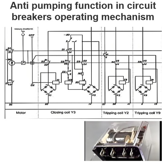
Anti-Jump Device Operation: Verify the operation of anti-jump devices.
General Performance: Ensure the equipment operates correctly within the specified supply voltage tolerances.
Grounding Terminal Inspection: Check the installation and connection of the circuit breaker's grounding terminal.
For circuit breakers equipped with undervoltage trip units, it should be verified that the circuit breaker can reliably trip and close when the voltage applied to the trip unit is within the specified limits.