• Product
  • Suppliers
  • Manufacturers
  • Solutions
  • Free tools
  • Knowledges
  • Experts
  • Communities
Search


How to handle transformer faults?

Felix Spark
Felix Spark
필드: Failure and maintenance
China

Common transformer faults and their handling methods.

1. Transformer Overheating

Overheating is extremely harmful to transformers. Most transformer insulation failures are caused by overheating. Rising temperature reduces the dielectric strength and mechanical strength of insulation materials. IEC 354, Loading Guide for Transformers, states that when the hottest spot temperature of a transformer reaches 140°C, bubbles will form in the oil. These bubbles can reduce insulation performance or cause flashover, leading to transformer damage.

Overheating greatly affects the service life of transformers. According to the transformer 6°C rule, within the temperature range of 80–140°C, for every 6°C increase in temperature, the rate at which transformer insulation effective service life is reduced doubles. National standard GB1094 also specifies that the average winding temperature rise limit for oil-immersed transformers is 65K, the top oil temperature rise is 55K, and the core and tank is 80K.

Transformer overheating mainly manifests as abnormal rise in oil temperature. Possible main causes include: (1) transformer overload; (2) cooling system failure (or incomplete engagement of cooling system); (3) internal transformer fault; (4) incorrect indication by temperature measuring device.

When abnormal rise in transformer oil temperature is detected, the above possible causes should be checked one by one to make an accurate judgment. Key inspection and handling points are as follows:

(1) If operational instruments indicate the transformer is overloaded, and the temperature gauges of the three phases in a single-phase transformer bank show basically consistent readings (with possible deviation of a few degrees), and the transformer and cooling system are operating normally, the temperature rise is likely caused by overload. In this case, strengthen monitoring of the transformer (load, temperature, operating status), immediately report to the higher-level dispatching department, and recommend transferring load to reduce overload magnitude and duration.

(2) If the temperature rise is due to incomplete engagement of the cooling system, the system should be immediately activated. If the cooling system has failed, the cause should be quickly identified and addressed immediately. If the fault cannot be resolved promptly, the transformer’s temperature and load must be closely monitored, reports must be made continuously to the dispatching department and production management, the transformer load should be reduced, and the transformer should operate according to the corresponding load value matching the cooling capacity under the current cooling condition.

(3) If the remote temperature measurement device issues a high-temperature alarm signal with a very high indicated value, but the local thermometer shows normal readings and there are no other signs of transformer faults, the alarm may be a false signal due to a fault in the remote temperature measurement circuit. Such faults can be rectified at an appropriate time.

(4) If in a three-phase transformer bank, the oil temperature of one phase rises significantly higher than its historical oil temperature under the same load and cooling conditions, and the cooling system and thermometer are normal, the overheating may be caused by an internal fault in the transformer. Professional personnel should be notified immediately to take an oil sample for chromatographic analysis to further identify the fault. If chromatographic analysis indicates an internal fault, or if the oil temperature continues to rise under unchanged load and cooling conditions, the transformer should be taken out of service according to the on-site regulations.

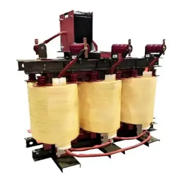
transformer.jpg

2. Cooling System Failure

The cooling system helps dissipate heat from the windings and core through transformer oil. 500kV main transformers all use forced oil circulation with forced air cooling. Whether the cooling system is operating normally is a critical condition for normal transformer operation. Cooling equipment failure is a common transformer fault. When cooling equipment fails, the transformer’s operating temperature rises rapidly, and the insulation life loss increases sharply. 

During cooling equipment failure, operators should closely monitor the transformer’s temperature and load, report continuously to the dispatching department and operation supervisors. If the transformer load exceeds the specified limit under faulty cooling conditions, load reduction should be requested according to on-site regulations.

It should be noted that during oil temperature rise, the core and windings heat up faster than the oil. The oil temperature may appear to rise only slightly, but the core and winding temperatures may already be very high. Especially when oil pumps fail, the temperature rise of windings relative to oil far exceeds the normal value specified on the nameplate. The oil temperature may appear to rise only slightly or not noticeably, while the core and winding temperatures may already far exceed allowable limits. 

Later, as oil temperature gradually rises, the core and winding temperatures will continue to rise to even higher values, maintaining a certain temperature rise over oil under the given load and cooling conditions. Therefore, when cooling equipment fails, not only should oil and winding temperatures be observed, but also the transformer’s allowable operating capacity and time under cooling system outage, as specified by the manufacturer and on-site regulations, should be followed. Other operational changes should also be monitored to comprehensively assess the transformer’s operating condition.

To check cooling equipment failure, determine the scope of the outage (individual fan or oil pump stopped, entire group stopped, single-phase or three-phase stopped), refer to the cooling system control circuit diagram to locate the fault point, and minimize the downtime of the cooling equipment.

If an individual fan or oil pump fails while others operate normally, possible causes include:

  • One phase of the three-phase power supply to the fan or oil pump is open-circuited (fuse blown, poor contact, or broken wire), causing increased motor current, thermal relay operation or power cutoff, or motor burnout;

  • Bearing or mechanical failure in the fan or oil pump;

  • Fault in the corresponding control relay, contactor, or other components in the fan or oil pump control circuit, or circuit break (e.g., loose terminal, poor contact);

  • Thermal relay setting too low, causing false operation.

If the cause is found to be a power supply or circuit fault, the broken wire should be quickly repaired, fuses replaced, and power and circuit restored. If the control relay is damaged, it should be replaced with a spare. If the fan or oil pump is damaged, maintenance should be requested immediately.

If a group (or several) fans or oil pumps stop simultaneously, the likely cause is a power supply fault to that group, blown fuse, thermal relay operation, or damaged control relay. The standby fan or oil pump should be immediately engaged, then the fault restored.

If all fans or oil pumps of a main transformer stop, it must be due to a failure in the main power supply to one or all three phases of the cooling system. In this case, check whether the standby power supply has automatically engaged. If not, manually engage the standby power supply quickly, identify the fault cause, and eliminate it.

When handling power supply faults and restoring power, pay attention to the following:

  • When replacing fuses, first open the circuit power and load-side switch or isolator. During live fuse replacement, when the second phase is installed, the three-phase motor receives two-phase power, generating a large current that may blow the newly installed fuse.

  • Use fuses with specifications and capacity matching the design.

  • When restoring power and restarting cooling equipment, start in steps or groups as much as possible to avoid simultaneous startup of all fans and oil pumps, which may cause current surge and blow fuses again.

  • After three-phase power is restored, if fans or oil pumps still do not start, it may be because the thermal relay has not been reset. Reset the thermal relay. If no fault exists in the cooling equipment, it should restart normally.

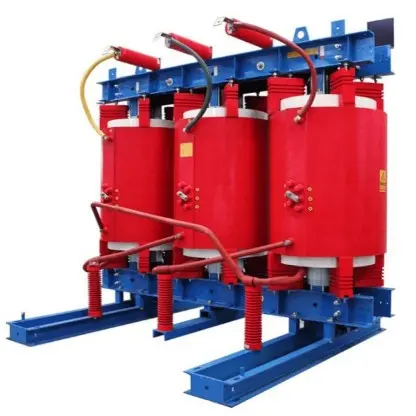
transformer.jpg

3. Abnormal Oil Level

Abnormal transformer oil level includes abnormal main tank oil level and abnormal on-load tap changer (OLTC) oil level. 500kV transformers generally use oil reservoirs with diaphragms or bladders, with pointer-type oil level gauges indicating the oil level. The oil level of both can be observed via the gauge.

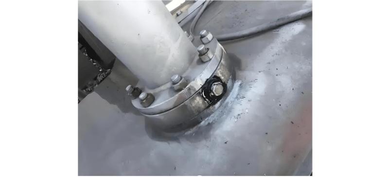
If transformer oil level is low, the cause should be investigated. If low oil level is due to low ambient temperature or light load causing oil temperature drop to the minimum oil level line, oil should be added promptly. If oil level drops due to serious oil leakage, measures should be taken immediately to stop the leak and add oil.

High transformer oil level may be caused by:

  • excessive oil filling, with oil level rising with temperature during high ambient temperature or high load; 

  • cooling system failure;

  • internal transformer fault.

When oil level is too high, check the load and oil temperature, confirm cooling system normality, verify all valve positions are correct, and check for any signs of internal faults. If oil level is excessively high or oil overflows, and no other faults are present, a small amount of transformer oil may be drained appropriately.

High oil level in the OLTC oil reservoir, besides oil temperature, may also be caused by overheating of electrical joints or other reasons causing seal failure in the OLTC compartment, allowing insulating oil from the main tank to leak into the OLTC compartment, causing abnormal rise in OLTC oil level. When OLTC oil level rises abnormally and continuously, even overflowing from the OLTC oil reservoir breather, immediately report to the dispatching department, have professionals conduct testing and analysis, request taking the faulty transformer out of service for maintenance.

500kV transformers generally use oil reservoirs with diaphragms or bladders and pointer-type oil level gauges, which indicate oil level based on the position of the diaphragm or bladder bottom. The following conditions may cause inaccurate pointer indication:

  • Gas accumulated under the diaphragm or bladder causes it to float above the actual oil level, resulting in higher oil level indication; 

  • Breather blockage prevents air from entering when oil level drops, causing higher oil level indication; 

  • Rupture of the bladder or diaphragm allows oil to enter the space above, possibly causing lower oil level indication.

These three situations may lead to incorrect oil level indication, requiring operators to carefully observe and analyze during normal operation.

transformer.jpg

4. Light Gas Relay Operation

When the light gas relay operates, it indicates abnormal transformer operation and should be inspected and handled immediately. Methods are as follows:

(1) Inspect the transformer’s appearance, sound, temperature, oil level, and load. If severe oil leakage is found and oil level is below the 0 mark on the gauge, possibly below the gas relay level that triggers alarm signals, the transformer should be immediately taken out of service and the leak repaired promptly.

If abnormal temperature rise or unusual operating sound is detected, there may be an internal fault. Transformer abnormal noise comes in two types: one caused by mechanical vibration, the other by partial discharge. A listening rod (or flashlight) can be used—press one end firmly against the casing and listen with the ear at the other end—to determine if noise originates from internal components (mechanical vibration or partial discharge). Discharge noise usually has a rhythmic pattern similar to corona noise on high-voltage bushings. If suspicious internal discharge noise is detected, immediately perform oil chromatographic analysis and intensify monitoring.

(2) Extract gas sample for analysis. Usually, on-site qualitative judgment is combined with laboratory quantitative analysis.

For gas sampling, use a syringe of appropriate volume. Remove the needle and attach a short piece of plastic or oil-resistant rubber tubing. Before sampling, fill the syringe and tubing with transformer oil to expel air, then push the plunger fully to expel the oil. Connect the tubing to the gas relay’s vent valve (ensure airtight connection). Open the gas relay vent valve and slowly pull back the syringe plunger to draw gas into the syringe.

Bring a flame near the syringe needle and slowly push the plunger to release the gas, observing whether the gas is flammable. Simultaneously, send the gas to the lab for gas composition analysis for accurate judgment.

If the gas is found flammable or chromatographic analysis confirms an internal fault, the transformer should be immediately taken out of service.

If the gas is colorless, odorless, and non-flammable, and chromatographic analysis identifies it as air, the gas relay alarm may be a false alarm due to secondary circuit fault. The circuit should be inspected and repaired promptly.

During gas sampling, use a colorless transparent syringe for easy observation of gas color. The procedure must be conducted under strict supervision, maintaining safe distance from live parts.

5. Transformer Tripping

When a transformer trips automatically, a comprehensive inspection should be conducted immediately to identify the cause before taking action. Specific inspection items include:

(1) Based on protective relay signals, fault recorder, and other monitoring device displays or printouts, determine which protection operated.

(2) Check load, oil level, oil temperature, oil color, and whether there is oil spraying, smoking, bushing flashover or rupture, pressure relief valve operation, or other obvious fault signs before tripping, and whether gas is present in the gas relay.

(3) Analyze the fault recorder waveform.

(4) Understand system conditions: whether short-circuit faults occurred inside or outside the protection zone, whether system operations or switching overvoltages occurred, or inrush current during closing.

If inspection shows the automatic trip was not caused by a transformer fault, the transformer may be re-energized after external faults are cleared.

If any of the following conditions are found, internal transformer fault should be suspected. The cause must be identified, the fault eliminated, and electrical tests, chromatographic analysis, and other targeted tests must confirm the fault is resolved before re-energizing:

(1) Gas extracted from the gas relay is confirmed flammable by analysis; (2) Obvious internal fault signs in the transformer, such as tank deformation, abnormal oil level, severe oil spraying; (3) Obvious flashover marks or damage, breakage on transformer bushings; (4) Two or more protective relays (differential, gas, pressure) operated.

6. Abnormal Noise

(1) If the noise is loud and noisy, it may be due to transformer core issues. For example, loose clamps or core-tightening bolts. Instrument readings are generally normal, and oil color, temperature, and level show no significant change. In this case, stop transformer operation and conduct inspection.

(2) If the noise contains a boiling water sound or "gurgling" bubble sound, it may indicate a serious winding fault causing nearby parts to overheat and vaporize oil. Poor contact in the tap changer causing local overheating or winding turn-to-turn short circuit can both produce this sound. Immediately stop transformer operation and perform maintenance.

(3) If the noise contains loud, irregular explosion-like sounds, it may indicate insulation breakdown in the transformer body. Stop operation and perform maintenance.

(4) If the noise contains a "zizi" discharge sound, it may be due to surface partial discharge on the transformer body or bushings. If it is a bushing issue, corona glow or small blue/purple sparks may be visible in poor weather or at night. Clean the bushing surface and apply silicone oil or silicone grease. Stop the transformer, and check whether core grounding and clearances between live parts and ground meet requirements.

(5) If the noise contains continuous, rhythmic knocking or rubbing sounds, it may be due to mechanical contact caused by vibration of certain components, or abnormal noise caused by electrostatic discharge.

7. Oil Spraying and Explosion

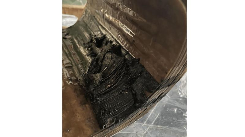
Oil spraying and explosion occur when internal fault short-circuit currents and high-temperature arcs rapidly age the transformer oil, and the protective relay fails to cut off power in time, allowing the fault to persist and internal tank pressure to continuously increase. High-pressure oil and gas then spray out from the explosion-proof pipe or other weak points of the tank, causing an accident.

(1) Insulation damage: Local overheating such as turn-to-turn short circuits damages insulation; transformer water ingress causes insulation moisture and damage; overvoltage such as lightning strikes damages insulation—these are basic factors leading to internal short circuits.

(2) Wire breakage causing arcing: Poor welding of winding conductors or loose lead connections may cause wire breakage under high current surge. High-temperature arcs at the break point vaporize oil, increasing internal pressure.

(3) Tap changer failure: In distribution transformers, the high-voltage winding tap section is connected via the tap changer. The tap changer contacts are in series in the high-voltage winding circuit and carry load and short-circuit currents. If the moving and stationary contacts overheat, spark, or arc, the tap section winding may short circuit.

8. Emergency Shutdown of Transformer

A running transformer should be immediately stopped if any of the following conditions are observed:

(1) Abnormal or significantly increased internal noise; (2) Severe damage and discharge on bushings; (3) Smoke, fire, or oil spraying from the transformer; (4) The transformer has a fault, but the protection device fails to operate or operates incorrectly; (5) Fire or explosion nearby poses a serious threat to the transformer.

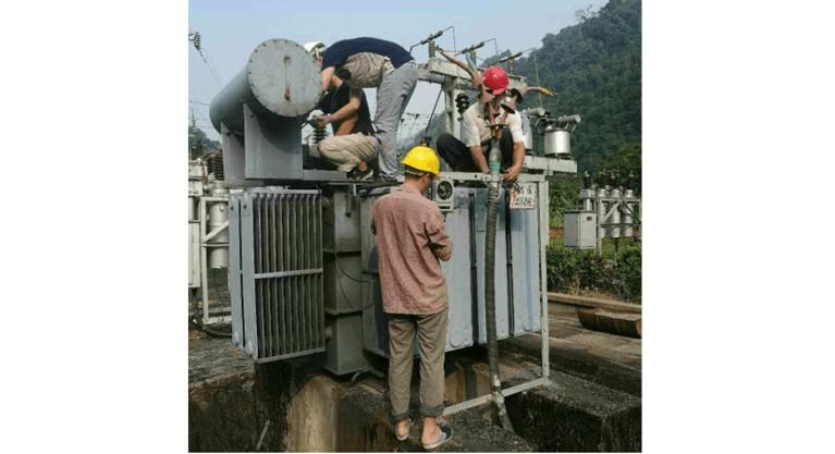
In case of transformer fire, immediately disconnect the power, stop fans and oil pumps, summon fire personnel immediately, and activate fire extinguishing equipment. If the fire is caused by insulating oil overflowing and burning on the top cover, open the lower drain valve to release oil to an appropriate level to stop overflow, preventing oil level from dropping below the cover and causing internal fire. If the fire is due to an internal fault, oil must not be drained, to prevent air from entering and forming an explosive mixture that could cause a severe explosion.

In summary, when a transformer fault occurs, accurate judgment and proper handling are essential—preventing fault escalation while avoiding unnecessary shutdowns. This requires improved diagnostic capability and accumulated operational experience to correctly identify and promptly handle transformer faults, preventing accident expansion.

Factors causing abnormal transformer noise are numerous, and fault locations vary. Only by continuously accumulating experience can accurate judgments be made.

작가에게 팁을 주고 격려하세요
10kV RMU Common Faults & Solutions Guide
Application Issues and Handling Measures for 10kV Ring Main Units (RMUs)The 10kV ring main unit (RMU) is a common electrical distribution device in urban power distribution networks, primarily used for medium-voltage power supply and distribution. During actual operation, various issues may arise. Below are common problems and corresponding corrective measures.I. Electrical Faults Internal Short Circuit or Poor WiringA short circuit or loose connection inside the RMU can lead to abnormal operati
Echo
10/20/2025
High-Voltage Circuit Breaker Types & Fault Guide
High-Voltage Circuit Breakers: Classification and Fault DiagnosisHigh-voltage circuit breakers are critical protective devices in power systems. They rapidly interrupt current when a fault occurs, preventing damage to equipment from overloads or short circuits. However, due to long-term operation and other factors, circuit breakers may develop faults that require timely diagnosis and troubleshooting.I. Classification of High-Voltage Circuit Breakers1. By Installation Location: Indoor-type: Insta
Felix Spark
10/20/2025
10 Prohibitions for Transformer Installation and Operation!
10 Prohibitions for Transformer Installation and Operation! Never install the transformer too far away—avoid placing it in remote mountains or wilderness. Excessive distance not only wastes cables and increases line losses, but also makes management and maintenance difficult. Never choose transformer capacity arbitrarily. Selecting the right capacity is essential. If the capacity is too small, the transformer may be overloaded and easily damaged—overloading beyond 30% should not exceed two hours
James
10/20/2025
How to Maintain Dry-Type Transformers Safely?
Maintenance Procedures for Dry-Type Transformers Put the standby transformer into operation, open the low-voltage side circuit breaker of the transformer to be maintained, remove the control power fuse, and hang a "DO NOT CLOSE" sign on the switch handle. Open the high-voltage side circuit breaker of the transformer under maintenance, close the grounding switch, fully discharge the transformer, lock the high-voltage cabinet, and hang a "DO NOT CLOSE" sign on the switch handle. For dry-type trans
Felix Spark
10/20/2025
관련 제품
문의 보내기
다운로드
IEE Business 애플리케이션 가져오기
IEE-Business 앱을 사용하여 장비 찾기 해결책 얻기 전문가 연결하기 업계 협업 참여 언제 어디서나 전력 프로젝트와 비즈니스 발전을 전폭 지원