What are the causes of dielectric withstand failure in vacuum circuit breakers?

Causes of Dielectric Withstand Failure in Vacuum Circuit Breakers:
Surface contamination: The product must be thoroughly cleaned before dielectric withstand testing to remove any dirt or contaminants.
Dielectric withstand tests for circuit breakers include both power-frequency withstand voltage and lightning impulse withstand voltage. These tests must be performed separately for phase-to-phase and pole-to-pole (across the vacuum interrupter) configurations.

Circuit breakers are recommended to be tested for insulation while installed in switchgear cabinets. If tested separately, the contact parts must be insulated and shielded, typically using heat-shrink tubing or insulating sleeves. For fixed-type circuit breakers, testing is generally conducted by directly bolting the test leads to the pole column terminals.
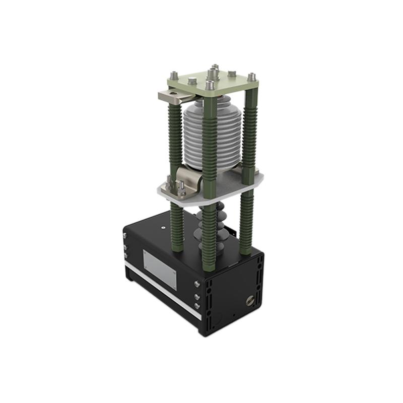
For solid-insulated pole columns with vacuum interrupters, the vacuum interrupter itself does not require sheds (skirts) to increase creepage distance. The vacuum interrupter is encapsulated within epoxy resin using silicone rubber, so the outer surface of the interrupter does not bear voltage. Instead, flashover occurs along the outer surface of the solid-insulated pole column. Therefore, the creepage distance between the upper and lower terminals of the solid-insulated pole column must meet requirements. For a pole-to-pole spacing of 210 mm, after deducting the contact arm diameter of 50 mm, the creepage distance cannot exceed 240 mm if no sheds are present.

Since the contact arm and the pole column terminal cannot be fully sealed, the sheds in this section are critically important. For 40.5 kV applications, with a pole-to-pole spacing of 325 mm, even adding sheds cannot satisfy the required creepage distance, making surface flashover highly likely. Therefore, it is generally necessary to use compressed silicone rubber to form a sealed solid insulation at the joint between the contact arm and the pole column, completely preventing surface tracking along the pole column end face. After this treatment, the creepage distance between the upper and lower poles via the contact arm can meet requirements, avoiding discharge.
If the external insulation clearance and creepage distance of the solid-insulated pole column are sufficiently large, discharge typically will not occur. Dielectric strength reduction is usually caused by loss of vacuum in the interrupter or complete failure of the pole assembly. Cracks or housing defects resulting from improper design or manufacturing, early material aging due to processing issues, or vibration-induced flashover/breakdown can also lead to equipment damage.
For insulation-cylinder-type pole columns, both the inner and outer walls of the insulating cylinder must be considered for creepage distance. Therefore, products with a pole spacing of 205 mm are generally not available. Additionally, the vacuum interrupter itself must also provide sufficient creepage distance to prevent flashover between the upper and lower poles.

Moreover, material hygroscopicity can also cause insulation test failure. Although epoxy resin has certain water resistance, prolonged exposure to humid or wet environments allows water molecules to gradually penetrate into the resin, leading to hydrolysis that breaks chemical bonds and degrades performance—such as reduced adhesion and mechanical strength.

| Test Item | Unit | Test Method | Index Value | |
| Color | / | Visual Inspection | As per specified color palette | |
| Appearance | / | Visual Inspection | Within limit | |
| Density | g/cm³ | GB1033 | 1.7-1.85 | |
| Water Absorption | % | JB3961 | ≤0.15 | |
| Shrinkage | % | JB3961 | 0.1-0.2 | |
| Impact Strength | JK/m² | GB1043 | ≥25 | |
| Bending Strength | Mpa | JB3961 | ≥100 | |
| Insulation Resistance | Normal State | Ω | GB10064 | ≥1.0×10¹³ |
| After Immersion for 24h | ≥1.0×10¹² | |||
| Electrical Strength | GB1408 | ≥12 | ||
| Arc Resistance | S | GB1411 | 180+ | |
| Comparative Tracking Index | / | GB4207 | ≥600 | |
| Flammability | / | GB11020 | FV0 | |
Water is a good conductor of electricity. After absorbing moisture, the dielectric constant of epoxy resin increases and its insulation resistance decreases, which may lead to electrical leakage, breakdown, and other failures in electrical equipment. Moisture-absorbed epoxy resin in circuit breaker pole columns can trigger partial discharge, thereby shortening equipment service life.
Under high electric fields, moisture accelerates the growth of electrical trees, further degrading insulation performance. This is a common cause of epoxy resin insulation failure in power equipment.
Moisture absorption also promotes reactions between epoxy resin and other environmental factors (such as oxygen, acidic or alkaline substances), accelerating material aging, which manifests as yellowing and embrittlement.
For high-current solid-insulated pole columns, heat sinks are typically installed on the upper part. These heat sinks are usually made of aluminum and coated with epoxy fluidized insulation on the outer surface. Due to the thin walls of the heat sink fins, the electric field intensity remains high at the top—even though rounded edges are provided—making discharge likely.
Generally, discharge may occur between the heat sink and the metal shutter. In such cases, attention must be paid to the electrical clearance between them. The shutter should avoid sharp edges; instead, bent flat surfaces or similar designs can be used to improve the electric field distribution.