Testing Methods for Newly Installed 35 kV GIS Gas-Insulated Switchgear

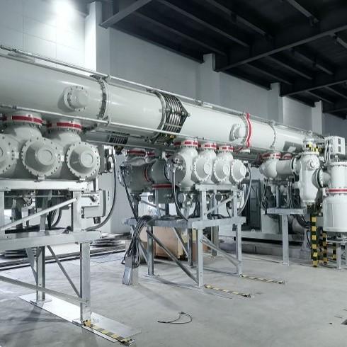
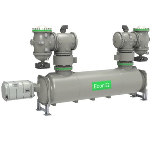
GIS (Gas-Insulated Switchgear) offers advantages such as compact structure, flexible operation, reliable interlocking, long service life, maintenance-free operation, and small footprint. It also possesses many irreplaceable advantages in insulation performance, environmental friendliness, and energy saving, and is increasingly applied in industrial and mining enterprises, airports, railways, subways, wind power stations, and other fields.
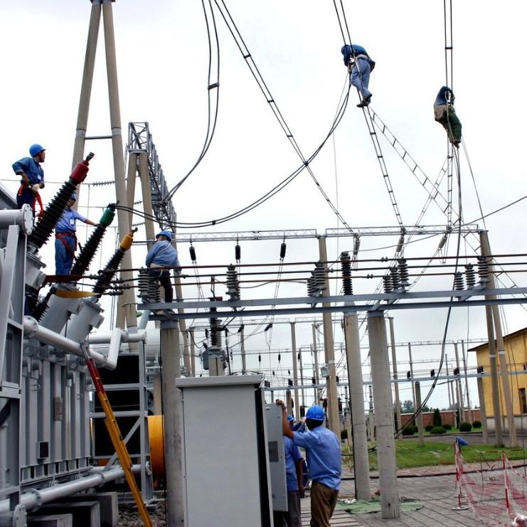
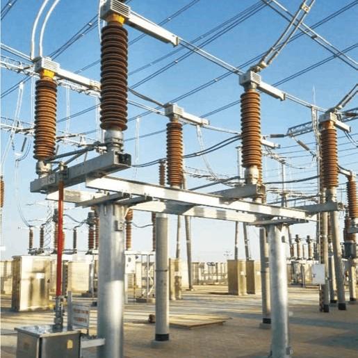
A certain enterprise’s 35 kV indoor substation was originally equipped with air-insulated switchgear comprising 10 bays. This upgrade adds 4 new bays. However, the original site area cannot accommodate the expanded bay requirements. Additionally, considering the equipment’s years in service and safety performance, the 35 kV substation is being retrofitted with SF₆ gas-insulated metal-enclosed switchgear. The existing switchgear room area can meet the expansion requirements, and the overall safety performance of the electrical equipment will be significantly improved.
This article studies, according to the main components of the switchgear, the following tests respectively: enclosure and busbar insulation tests, vacuum circuit breaker tests, voltage transformer tests, current transformer tests, metal oxide surge arrester tests, and power cable tests.
1.Test Item Classification and Sequence Arrangement
The Bus Section III of a 35 kV substation consists of a double-bus system formed by 14 ZX2-type SF₆ gas-insulated switchgear units. All primary live parts inside the cabinets are installed within sealed gas-filled enclosures, making direct preventive testing difficult. Testing must therefore be conducted by forming test circuits using adjacent switchgear units. Many conductive parts, such as voltage transformers and busbars, use plug-in connections. To ensure good contact at all busbar plug joints, DC contact resistance measurements must be performed on all joints. During testing, temporary test plugs must be installed at cable sockets to serve as test access points, which increases test difficulty and workload. Therefore, the test sequence should be reasonably arranged to minimize workload. Considering the above factors, electrical equipment testing for the 35 kV Bus Section III is implemented via two methods: internal cabinet tests and external cabinet tests.
2. Characteristic Tests of Equipment Inside the Switchgear
Internal cabinet tests are carried out in two rounds. In the first round, low-voltage current injection test plugs are used; these plugs are easy to install—simply inserted directly into the cable installation sockets inside the switchgear. In the second round, high-voltage test plugs are inserted into the cable installation sockets inside the switchgear and secured with screws to introduce test voltage into the equipment under test.
2.1 First Round Tests
2.1.1 Vacuum Circuit Breaker Tests
In this round, mechanical characteristic tests and operating mechanism tests are performed first, both using a circuit breaker dynamic characteristic tester. Two adjacent switchgear units are grouped together. Three-phase test leads are connected at one end, and the other end is grounded. The mechanical characteristics and coil operating voltages of the two series-connected circuit breakers are measured separately—i.e., when measuring the mechanical characteristics of one circuit breaker, the other circuit breaker is closed to serve as the test path. The test method is identical to standard procedures. For the bus-tie breaker bay 9AH, which bridges the main and auxiliary buses of the double-bus system, it can be connected in series with the left-side breaker 10AH and the right-side breaker 8AH (three breakers total) to utilize the test paths of 10AH and 8AH.
2.1.2 DC Contact Resistance Test of Conductive Circuits and Bus Plug Joints
To measure the contact resistance of all vacuum circuit breakers, main/auxiliary bus disconnect switches, and main/auxiliary bus plug joints, adjacent switchgear units are still grouped in pairs, but tested sequentially—i.e., 1AH–2AH, 2AH–3AH, ..., 13AH–14AH. For each pair, when the main (or auxiliary) bus disconnect switches of the two adjacent switchgear units are closed, the three-phase DC contact resistance of the corresponding main (or auxiliary) bus path is measured. A loop resistance tester is used with a test current of approximately 100 A. For example, for the bus-tie breaker 9AH, it can similarly be connected in series with the left-side 10AH and right-side 8AH to form two test paths: 10AH–main bus–9AH–auxiliary bus–8AH and 10AH–auxiliary bus–9AH–main bus–8AH. The test method is the same as for other switchgear units, with resistance values ranging from 200 to 300 μΩ.
2.1.3 Current Transformer Tests
The primary conductive parts of the gas-insulated dedicated current transformers installed inside the cabinet are sealed within the enclosure; therefore, their tests must be completed simultaneously during internal cabinet testing. In this round, ratio tests, polarity checks, and excitation characteristic curve tests are performed first. These tests are carried out using a multifunctional fully automatic comprehensive transformer tester.
For ratio tests and polarity checks: the test circuit configuration is consistent with that of the circuit breaker mechanical characteristic tests—i.e., two adjacent switchgear units are grouped, with their circuit breakers and same-side bus disconnect switches closed. High current is injected phase by phase, and secondary induced currents are drawn from the corresponding secondary current terminals to measure the ratio and polarity of all current transformers connected in series in the loop. The test method is identical to standard procedures.
For the excitation characteristic curve test: this test only requires the primary circuit to be open and can be performed at any time. Considering that it uses the same test equipment and shares the same secondary current terminals as the ratio test—i.e., test current is injected through the corresponding secondary current terminals—it can be performed simultaneously with the ratio test to improve work efficiency.
2.2 Insulation Tests of Equipment Inside the Switchgear
In the second round of tests, insulation tests of the switchgear and busbars are performed simultaneously, including: insulation tests of circuit breaker live parts to ground and across contacts, insulation tests of main/auxiliary bus disconnect switch live parts to ground and across contacts, insulation tests of current transformer primary to secondary and to ground, and insulation tests of all internal main/auxiliary busbars and conductive parts to ground and between phases.
Each switchgear unit is subjected to voltage application twice. First, the main and auxiliary busbars inside the cabinet are grounded through a selected switchgear unit—i.e., the circuit breaker and either the main (or auxiliary) bus disconnect switch of the selected switchgear unit are closed. Then, the bus-tie circuit breaker and its main/auxiliary bus disconnect switches are closed, and a temporary grounding wire is installed at the cable socket of that switchgear unit, thereby grounding the entire main and auxiliary busbar system inside the cabinet.
The switchgear unit under test uses a high-voltage test plug, which is screwed tightly into the cable socket to introduce the test voltage.
During the first voltage application to the switchgear unit, its circuit breaker is open, and the three-position main bus disconnect switch is set to the grounding position (or set to the service position with the bus grounded elsewhere), allowing withstand voltage tests between the current transformer primary-to-secondary and primary-to-ground, as well as across the circuit breaker contacts.
During the second voltage application, the circuit breaker is closed, and both the main and auxiliary bus three-position disconnect switches are in the open position, enabling withstand voltage tests of the entire circuit breaker assembly to ground and across the main/auxiliary bus disconnect switch contacts.
For the special bus-tie circuit breaker bay 9AH, the tests can be scheduled together with the main and auxiliary bus withstand voltage tests, requiring a total of three voltage applications. During the first voltage application, the bus-tie circuit breaker and the main bus disconnect switch are closed, while the auxiliary bus disconnect switch is open. The auxiliary bus is grounded through another switchgear unit, and the test voltage is introduced into the main bus via a certain switchgear unit. Withstand voltage tests are then performed on the main bus system, the entire bus-tie circuit breaker to ground, and the auxiliary bus disconnect switch contact gap, as shown in Figure 1.

During the second voltage application, the bus-tie circuit breaker and the auxiliary bus disconnector are closed, while the main bus disconnector is opened. The main bus is grounded through another switchgear unit, and the test voltage is introduced into the auxiliary bus via a certain switchgear unit. A withstand voltage test is then performed on the auxiliary bus system, the entire bus-tie circuit breaker to ground, and the contact gap of the main bus disconnector.
During the third voltage application, the contact gap of the bus-tie circuit breaker is tested via the auxiliary bus. Specifically, the bus-tie auxiliary bus disconnector is closed, the bus-tie circuit breaker is opened, and the bus-tie main bus disconnector is set to the “ground” position. The test voltage is introduced into the auxiliary bus through a certain switchgear unit to perform the withstand voltage test on the contact gap of the bus-tie circuit breaker.
3.Tests Conducted Outside the Switchgear
For equipment such as surge arresters, voltage transformers, and cables, all tests are completed prior to installation.
3.1 Metal-Oxide Surge Arrester Tests
All circuit breaker bays on the 35 kV Bus Section III (except the bus-tie bay) are equipped with metal-oxide, gapless, shielded, plug-in surge arresters. Testing is performed before arrester installation. Insulation resistance is measured both before and after the test. A DC high-voltage generator is used, and tests are conducted according to manufacturer specifications:
DC reference voltage at 1 mA ≥ 73 kV
Leakage current at 75% of U₁ₘₐ ≤ 50 μA
During testing, a dedicated insulating sleeve must be installed on the high-voltage terminal of the arrester; otherwise, in ambient air, surface flashover will occur due to high voltage and small clearance, damaging the arrester’s surface insulation—making the test impossible and risking equipment damage.
3.2 Voltage Transformer (VT) Tests
A total of 14 single-phase, plug-in, gas-insulated cabinet-specific voltage transformers are installed on the 35 kV Bus Section III. Bus VTs differ from line VTs in that they include an additional residual winding for zero-sequence voltage measurement.
Ratio and Polarity Tests: A multifunctional CT/VT tester is used to measure the voltage ratio between the primary winding and each secondary winding (including the residual winding) and verify polarity relationships.
Excitation Characteristic Curve: Using the same tester, excitation voltage is applied to the secondary winding, and the excitation curve is recorded at 20%, 50%, 80%, 100%, and 120% of the secondary rated voltage (i.e., 20 V, 50 V, 80 V, 100 V, and 120 V).
During testing, a temporary insulating cap (inner cone insulator) must be installed on the primary high-voltage terminal; otherwise, surface flashover will occur, damaging the insulation and preventing the test voltage from being reached.
DC Resistance of Windings: The DC resistance of both primary and secondary windings of each VT is measured.
AC Withstand Voltage Test: Since these VTs are designed specifically for gas-insulated switchgear, their external insulation cannot withstand high test voltages when tested outside the cabinet. Therefore, no power-frequency AC withstand test is performed on the primary winding. Instead, an induced voltage test is used. This induced test can be combined with the excitation characteristic test—applying voltage for 1 minute at 120 V on the secondary side.
Apply 3 kV AC (power frequency) for 1 minute between the primary winding terminal N and all other windings/ground.
Apply 2 kV AC (power frequency) for 1 minute between each secondary (or residual) winding and all other windings/ground.
Tests on Auxiliary Components: Measure the DC resistance of the primary-side fuse of each VT and check the insulation resistance of the neutral-point spark gap protector.
4.Precautions During Testing
4.1 Basic Conditions Before Testing
The SF₆ gas pressure gauge must indicate within the normal green range.
The switchgear enclosure must be reliably grounded, with grounding resistance meeting requirements.
Verify that the actual positions and status indicators of three-position disconnectors and circuit breakers are correct.
All unused sockets on the equipment under test must be sealed with insulating plugs.
During AC withstand tests, cable termination holes, arrester mounting holes, and VT mounting holes in bays receiving voltage must be sealed with dedicated insulating plugs; non-energized areas do not require sealing.
Confirm that the busbar ends are sealed with insulating plugs and that both end cabinets are fully enclosed.
4.2 Special Characteristics of High-Voltage Tests
Due to insufficient external insulation strength of VTs outside the cabinet, the induced voltage test on the primary winding must be combined with the excitation test at reduced voltage, which does not fully replicate standard withstand conditions. Additionally, DC contact resistance measurements reflect the total resistance of the entire series path—including circuit breakers, disconnectors, bus plug joints, and CT primaries—making it difficult to pinpoint which specific component exceeds allowable limits if the total value is out of specification.
4.3 Special Nature of High-Voltage Test Methods
Because direct testing of equipment sealed inside gas-filled enclosures is impossible, test circuits must be formed using adjacent switchgear units and busbars. Therefore, comprehensive testing of the entire 35 kV Bus Section III can only be performed when the bus system is de-energized. However, certain tests can be conducted on individual de-energized bays:
All CT tests (except ratio tests)
Withstand tests on circuit breaker contact gaps and line-side sections
Mechanical characteristic tests of circuit breakers (except the bus-tie breaker)
All tests on removable components such as cables, surge arresters, and VTs
4.4 Special Considerations for Test Standards
During internal AC withstand tests, since circuit breakers, disconnectors, CTs, and busbars are tested simultaneously, the test voltage must be limited to the lowest withstand rating among them—76 kV (the CT standard)—resulting in lower-than-optimal stress levels for other components. After removing secondary windings for testing, original wiring must be promptly restored to avoid poor contact or open circuits.
5.Conclusion
High-voltage testing of compact gas-insulated switchgear involves unique challenges and highly complex operational requirements. Therefore, a thorough understanding of equipment characteristics is essential. Selecting appropriate test equipment and methodologies tailored to these features, and summarizing effective testing procedures and standards, provides valuable reference and technical basis for resolving similar engineering challenges.